50960025/CP0514
28
PRINTED IN U.S.A.
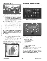
G - Hazard:
This switch can be activated to make the
tail lights flash on and off in case the machine is stalled
or temporarily stopped in a traffic area on the road or
jobsite.
H - Strobe Light:
When a stobe light is installed on
the machine, activating this switch will produce a
strobe light on and off flashing, for working in condi-
tions that may obscure view of the machine.
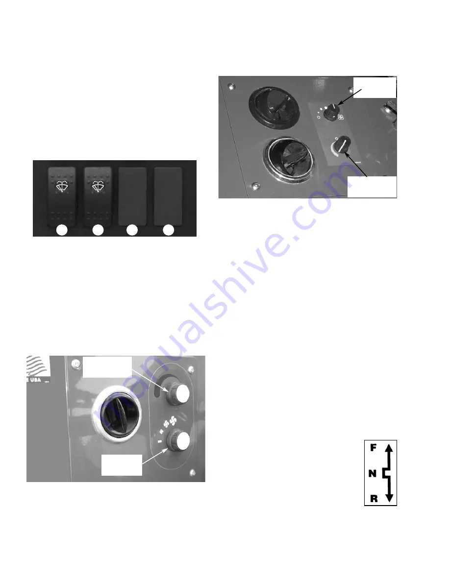
Bottom Row Switches
Switches have graphic symbols to indicate function
and effect. The following descriptions start with the
first switch on the left.
NOTE:
Some switches are optional and may not
be on machine.
I1 and I2 - Wiper/Washer:
The windshield and top
window of the operator’s station are each equipped
with a wiper and washer mechanism. Switch “I1”oper-
ates the wiper and washer on the windshield; switch
“I2” operates the wiper and washer on the top window.
J- K - Blank:
Heater Controls
Temperature Control:
This is the upper knob located
to the left of the steering wheel. This knob is used to
adjust the temperature output of the heater. Turning the
knob clockwise will increase the temperature output of
the cab heater.
Fan Speed:
This knob is located below the tempera-
ture control knob. Rotating the knob clockwise will
increase the fan speed for increased air circulation.
Heater A/C Controls
Fan Speed:
This is the upper knob located to the left
of the steering wheel. The fan is in the off position
when the knob is rotated completely to the left.
Rotating the knob clockwise will switch the fan on and
increase the fan speed for increased air circulation.
Temperature Control:
This knob is located below the
fan speed knob. It is used to adjust the temperature out-
put of the heater A/C unit. Turning the knob clockwise
from the midpoint position will increase the tempera-
ture output of the cab heater. Turning the knob counter-
clockwise from the midpoint position will switch the
A/C unit on and decrease the temperature output of the
cab A/C.
Travel Lever
Located on the left side of the steering wheel column,
this lever is used to change travel direction (forward or
reverse) and speed range.
Travel Direction:
The lever MUST be in “N”
(Neutral) position before the starter will engage to start
the engine.
NOTE:
Backup alarm automatically sounds with
travel lever in “R” (Reverse).
Position “F” (Forward)
Position “N” (Neutral)
Position “R” (Reverse)
I1
I2
J
K
Fan Speed
Knob
Temperature
Control Knob
Fan Speed
Knob
Temperature
Control Knob

