background image

OPERATION

Printed in U.S.A. 

97

50950436

/

H0521

Fig. 54 -  Rear Tie Down / Retrieval Points

5 . 

Fasten the machine to the hauling vehicle 
at the points indicated by the tie-down 
decals (Fig . 53 and Fig . 54) .

6 . 

Measure the clearance height of the 
machine and hauling vehicle . Post the 
clearance height in the cab of the vehicle .

When towing a machine:

1 . 

Connect the towline to both tie down/
retrieval points at the front or the rear 
of the machine . Use of only a single 
retrieval point or connecting the towline 
to any point on the machine other than the 
designated retrieval locations could result 
in machine damage .

2 . 

The towline strength is at least 1 .5 times 
the gross weight of the machine . The 
towline length is such that the maximum 
towing angle does not exceed 20° .

Loading and Transporting the 
Machine on a Transport Vehicle

Do not exceed the transport vehicle’s 
gross weight rating and the gross axle 
weight rating when loading and trans-
porting the machine. The transport 

vehicle must have sufficient capacity 

for the size and weight of the machine. 

Refer to “Specifications” on page 37.

Make sure the load does not fall 
short of the minimum axle load of the 
steering axle, otherwise the transport 
vehicle’s steering could be seriously 

affected.

Remove any mud, snow or ice from 
the tracks on the machine to prevent 
slipping.

Position the machine at the lowest 
possible position on the transport 
platform, with the center of gravity of 
the load over center line of the trans-
port vehicle. Distribute partial loads to 
ensure an even load on the axles on 
the transport vehicle.

Secure the machine properly so it 
cannot slip, slide, roll, tip over or fall, or 
cause the transport vehicle to tip over 
under transport conditions. Use anti-
slip bases and linings, load-securing 
straps and chains, clamping beams, 
protective pads, nets, edge protectors, 
etc. as needed to properly secure the 
load. Consider all possible transport 
conditions such as: heavy braking, 
evasive maneuvers, and uneven or 
rough roadways. 

Adjust transport speed to the load, to 

the road/traffic conditions and to the 

handling of the transport vehicle

Always use the proper tie-down points 
when using straps and chains.

Summary of Contents for MUSTANG 1050RT

Page 1: ...1050RT 1050RT EU 1050RT X Series CompactTrackLoader Operator s Manual 50950436 Rev H 05 21 Original Instructions ...

Page 2: ...sel engine exhaust exposes you to chemicals known to the state of California to cause cancer and birth defects or other reproductive harm Always start and operate the engine in a well venti lated area If in an enclosed area vent the exhaust to the outside Do not modify or tamper with the exhaust system Do not idle the engine except as necessary For more information go to www P65warnings ca gov die...

Page 3: ...S NOT INCLUDE 1 Transportation to selling dealer s business location or at the option of the Original Retail Purchaser the cost of a service call 2 Used equipment 3 Components covered by their own non MANITOU Group warranties such as tires batteries trade accessories and engines 4 Normal maintenance service and expendable high wear items 5 Repairs or adjustments caused by improper use failure to f...

Page 4: ...11 Indicator and Operation Symbols 12 SAFETY 15 Safety Symbol and Signal Words 15 Mandatory Safety Shutdown Procedure 16 Before Starting 17 During Operation 18 Applications with Load Handling Devices 20 Parking the Machine 21 Electrical Energy 21 Maintenance and Service Safety Practices 22 Battery Hazards 24 Fire Hazards 24 Additional Safety Equipment 25 Crystalline Silica Exposure 25 DECALS 27 Ge...

Page 5: ...Travel Controls 57 Lift Arm Float 57 Emergency Lift Arm Lower 57 Parking Brake Hydraulics Transport Lockout 57 Horn 58 Cab Heat Option 58 Windshield Wiper Washer 58 Beacon Option 59 Battery Disconnect Switch 59 OPERATION 61 Operational Checks Pre start Inspection 61 Before Operation 62 Seat Belt 62 Starting the Engine 63 Engine Warm Up 65 Run In Period 66 Stopping the Engine 66 Engine Stalling 66 ...

Page 6: ... DPF Regeneration Procedures After Operation Jump Starting Lifting the Machine using a Crane Towing Transporting the Machine Loading and Transporting the Machine on a Transport Vehicle Long Term Storage Final Shutdown Decommissioning LUBRICATION Types of Lubricants Lubricant Capacities Lubrication Points and Decals Lubrication Schedule Intervals Filter Table MAINTENANCE Maintenance Schedule Mainte...

Page 7: ... Maintenance Log 126 Maintenance Log 127 TROUBLESHOOTING 129 Engine Troubleshooting 129 Indicator Lamp Troubleshooting 131 Seal and Hose Troubleshooting 132 Hydraulic System Troubleshooting 132 Hydrostatic Travel Drive System Troubleshooting 135 Electrical Troubleshooting 137 Error Codes 139 Index 145 Torque Specifications 149 ...

Page 8: ...ry IMPORTANT The word IMPORTANT indicates situations that can result in possible damage to the machine NOTE The word NOTE indicates special or particularly useful information Contents and Use of this Manual This operator s manual provides informa tion about the safe and proper operation and maintenance for the machine Major points of safe operation and maintenance are detailed in the Safety chapte...

Page 9: ...dered contrary to the intended use Compliance with and strict adherence to the conditions of operation service and repair as specified by the manu facturer also constitute essential elements of the intended use 50950436 G0121 The machine was designed and built accord ing to the best available technology and approved safety regulations in the countries where it is sold However it is impossible to c...

Page 10: ..._____ Component Serial Numbers Engine Model Number _______________________________ Engine Serial Number _______________________________ Track Drive Motor Model Number _______________________________ Track Drive Motor Serial Number _______________________________ Hydraulic Pump Model Number _______________________________ Hydraulic Pump Serial Number _______________________________ ...

Page 11: ...Introduction 50950436 G0121 8 Printed in U S A Component Identification Fig 1 A B C D E F G H I Machine Components J K K L M N O P Item Description A Upright B Lift Cylinder C Tracks ...

Page 12: ...uckets Weight Rated Operating Capacity 1372 mm 0 28 m 54 00 in 9 8 ft 129 kg 285 lbs 476 kg 1050 lbs 1524 mm 0 31 m 60 00 in 11 0 ft 138 kg 305 lbs 467 kg 1030 lbs 1549 mm 0 33 m 61 00 in 11 6 ft 141 kg 310 lbs 465 kg 1026 lbs Pallet Forks Weight Rated Operating Capacity 406 4 mm 16 00 in Forks with Backrest Rating per EN474 3 213 kg 470 lbs 319 kg 704 lbs 508 mm 20 00 in Forks with Backrest Ratin...

Page 13: ... can be more efficient productive and safe An operator s exposure to vibration occurs in two ways Whole Body Vibration WBV Hand Arm Vibration HAV WBV issues are primarily addressed in this manual because evaluations have shown that operation of mobile compact construc tion equipment on work sites typically results in HAV levels less than the allowed exposure limit of 2 5 m s2 Member States of the ...

Page 14: ...pera tor s position 3 Maintain the work site Smooth ruts and fill potholes in traffic areas whenever possible Clean up debris frequently Vary traffic patterns to avoid exposure to rough terrain 4 Maintain equipment Check that seat suspension and all controls work smoothly and properly Vibration Levels See Vibration Levels on page 43 for a table listing typical whole body vibration levels for the m...

Page 15: ...Brake Engine Air Filter Engine Oil Engine Oil Filter Engine Oil Pressure Fuel Filter Engine Temperature Hydraulic System Hydraulic Oil Temperature Hydraulic Oil Filter Grease Lubrication Point Glow Indicator Lamp Diesel Fuel Clockwise Rotation Counterclockwise Rotation Fast Slow Ride Control Engine Malfunction Shutdown Bucket Float Bucket Rollback Bucket Dump Lift Arm Lower Lift Arm Raise Service ...

Page 16: ...otating Fan Keep Away Safety Lock Auxiliary Hydraulics Flow Fan Lift Arm Float Hitch Lock Hitch Unlock Heater Engine Temperature Critical Error Warning Engine Error Code Lock Unlock Front Window Washer Rear Window Washer Front Window Wiper Rear Window Wiper Beacon Regeneration Regeneration Inhibit Aftertreatment Error ...

Page 17: ... controlled by Manitou In any case the following activities are strictly prohibited any extraction reproduction representation reuse by making available to the public diffu sion or transfer whether permanent or temporary on any support and by any means and in any form whatsoever of all or a qualitatively or quantitatively substantial part of the contents of the database any extraction reproduction...

Page 18: ... sible damage to the machine NOTE The word NOTE indicates spe cial or particularly useful information Before operating the machine first read and study the safety information in this manual Be sure that anyone who oper ates or works on the machine is familiar with the safety precautions This includes providing translations of the warnings and instructions for operators who are not fluent in readin...

Page 19: ...nd panels are secured in the proper oper ating positions before starting the engine to operate the machine Mandatory Safety Shutdown Procedure BEFORE cleaning adjusting lubricating fueling or servicing the machine or leaving it unattended 50950436 H0521 1 Bring the machine to a complete stop on a level surface If the machine must be parked on a slope park across the slope and chock the tracks to p...

Page 20: ... with non approved attachments Optional kits are available through your dealer Because Manitou cannot antici pate identify and test all of the attach ments owners may want to install on their machines please contact Manitou Group for information on approval of attachments and their compatibility with optional kits Remove all trash and debris from the machine every day especially in the engine comp...

Page 21: ... hair jewelry or loose personal items while operating or servicing the machine During Operation ALWAYS fasten the seat belt securely and properly Never operate the machine without the seat belt fastened around the operator Only start the engine and only operate the controls while seated in the operator s seat Wear safety goggles ear and head protec tion and any other protective clothing or equipme...

Page 22: ...oving the ignition key Stop the engine and place the controls in the lock out position before mounting attachments Check that attachments are securely fastened to the lift arm before working Be aware that attachments affect the han dling and balance of the machine Adjust the operation of the machine as necessary when using attachments Before coupling or uncoupling the hydraulic lines for the attac...

Page 23: ...one near the machine is at risk of being injured Unless necessary for servicing the machine the engine hood must not be opened while the engine is running In cold weather avoid sudden travel movements and stay away from even slight slopes The machine can slide sideways on icy slopes Snow accumulation can hide potential hazards Use care while operating and while using the machine to clear snow If t...

Page 24: ...n Procedure on page 18 Electrical Energy Stay away from high voltage lines Electrocution can result from contact or proximity to high voltage electric lines The machine does not have to make phys ical contact with power lines for current to be transmitted Use a spotter and hand signals to keep away from power lines not clearly visible to the operator If the machine comes into contact with a live w...

Page 25: ...fety glasses with side shields when striking metal against metal In addition it is recommended that a softer chip resistant material be used to cushion the blow otherwise serious injury to the eyes or other parts of the body could result Use care when seating retainer pins retainer pins can fly out or splinter when struck and could cause injury Do not smoke or have any spark or flame producing equ...

Page 26: ...municipal waste collection containers or in metropolitan sewer systems or land fills Check state and local regulations for other requirements All safety equipment must be maintained so it is always in good condition Safety critical parts must be periodi cally replaced Replace the following potentially fire related components as soon as they begin to show signs of deterioration Fuel system flexible...

Page 27: ...frozen battery before charging it or attaching jumper cables Flush eyes with water for 10 15 minutes if battery acid is splashed in the face Anyone swallowing battery acid must have immediate medical aid Call the Poison Control Center at 1 800 222 1222 in the United States Fire Hazards The machine must be cleaned on a regu lar basis to avoid the buildup of flam mable debris such as leaves straw et...

Page 28: ...t if conditions require For example when using a hydraulic breaker a polycarbonate front window may be required Never attempt to alter or modify the pro tective structure by drilling holes welding or re locating fasteners Any serious impact or damage to the system requires a complete integrity re evaluation and the replacement of the system may be necessary Laminated glass or polycarbonate protec ...

Page 29: ...e Manitou Interface and Logistics Europe 5 Address Rue DesAndains 2 Perwez 1360 Belgium 6 We hereby declare that the machine listed below conforms to EC Directives 2014 30 EU EMC 2006 42 EC Machinery and 2000 14 EC Noise Emission as amended by 2005 88 EC 7 In accordance with EN ISO Standards EN474 1 and EN474 3 8 Designation EARTH MOVING MACHINERY LOADERS COMPACT 9 Model 1050RT 10 Serial Number 11...

Page 30: ...st be free of dirt dust grease and foreign material before applying the decal Remove the smaller portion of the decal backing paper and apply the exposed adhesive to the clean surface maintaining proper position and align ment Peel the rest of the backing paper and apply hand pressure to smooth out the decal surface Refer to the following pages for proper decal locations If replacing a part that h...

Page 31: ... Common Decals A Located next to the fuel filler neck USE PROPER DIESEL FUEL ONLY B Located on the bottom of the side panels behind the tracks both sides and at the front of each pontoon on the outside face both sides Tie down point Only use tie down points indi cated on machine when transporting machine ...

Page 32: ...arting fluids to start this engine warranty may be voided F Located on the inside of the left lift arm pillar Service Decal ANSI Style Decals G Hose removal or coponent failure can cause lift arm to drop Always use lift arm support device when leaving lift arm raised for service 137637 DANGER Located on lift arm support device machine left side WARNING Crush Hazard Be sure lock mechanism is secure...

Page 33: ...h speed turns Travel up and down slopes with heavy end uphill J AVOID INJURY OR DEATH Keep out from under work tool unless lift arm is supported No riders Never use work tools as work platform 137655 DANGER Located on front of the machine 50950436 H0521 DANGER AVOID INJURY OR DEATH Keep out from under work tool unless lift arm is supported No riders Never use work tool as work platform K Located o...

Page 34: ... is responsible to ensure all users are instructed on safe use and maintenance Check machine before operating Service per Operator s Manual Contact dealer or manufacturer for informa tion and service parts O Located on the rear window Designates emergency egress location P WARNING Located on the fan shroud inside the engine compartment WARNING ROTATING FAN Keep hands out or stop engine Q WARNING L...

Page 35: ...OPS FOPS left panel WARNING This product can expose you to lead which is known to the State of California to cause cancer and birth defects or other reproductive harm U Located on ROPS FOPS left panel WARNING Breathing diesel engine exhaust exposes you to chemicals known to the State of California to cause cancer and birth defects or other reproductive harm Always start and operate the engine in a...

Page 36: ...OR DEATH Maintain 3 point contact during entry and exit Inspect work area avoid all hazards Look in the direction of travel Keep children an bystanders away Start and operate machine only from the operator s seat Never carry riders Do not lift personnel in bucket Operate only in well ventilated area Keep away from electric power lines avoid contact Do not wear loose clothing while operating or ser...

Page 37: ... avoid fire Keep fire extinguisher nearby Do not use hands to find hydraulic leaks Escaping oil under pressure can be invisible and penetrate skin Allow radiator to cool before removing cap Loosen cap slowly to avoid burns Keep guards screens and windows in place Do not smoke while fueling or servicing machine L Located on ROPS FOPS left panel WARNING AVOID INJURY OR DEATH Always follow Mandatory ...

Page 38: ...on and service parts M Located on the fuel tank inside the engine compartment WARNING ROTATING FAN Keep hands out or stop engine WARNING HOT SURFACE Do not touch hot engine or hydraulic system parts N Located on lift arm support device machine left side WARNING Crush Hazard Be sure lock mechanism is securely engaged before working under ROPS FOPS Read instructions for use in Operator s Manual O Lo...

Page 39: ...ine WARNING AVOID INJURY OR DEATH Before operating with attachment check engagement of loader attachment bracket locking pin to the attachment R Located on the front of the machine WARNING AVOID INJURY OR DEATH Before operating with attachment check engagement of loader attachment bracket locking pin to the attachment S 50352526 Located on the fuel tank inside the engine compartment WARNING HOT SU...

Page 40: ... required Diesel Fuel Tank DPF Non DPF Tier 4 engines ULSD1 low sulfur or ultra low sulfur below 15 PPM 36 L 9 5 U S gallons DPF 39 L 10 3 U S gallons Non DPF Engine Coolant Long life coolant ASTM D4985 D6210 United States SAE J814C J1941 J1034 or J2036 international 6 62 L 1 75 U S gallons Radiator Cap Pressure 1 BAR 14 psi Engine Oil with filter API CK 4 preferred API CJ 4 SM acceptable Conventi...

Page 41: ...ed 2134 mm 84 0 in F Maximum Rollback Angle Fully Raised 102 G Overall Height Top of ROPS 1816 mm 71 5 in H Overall Length with Bucket w o Counterweight 2985 mm 117 5 in I Overall Length without Bucket w o Counterweight 2258 mm 88 9 in J Specified Height 1466 mm 57 7 in K Reach at Specified Height 991 mm 39 0 in L Dump Angle at Specified Height 72 M Maximum Rollback Angle at Ground 32 N Carry Posi...

Page 42: ... front face of the forks to the center of mass of the load Dirt Construction Buckets Weight Rated Operating Capacity 1372 mm 0 28 m 54 00 in 9 8 ft 129 kg 285 lbs 476 kg 1050 lbs 1524 mm 0 31 m 60 00 in 11 0 ft 138 kg 305 lbs 467 kg 1030 lbs 1549 mm 0 33 m 61 00 in 11 6 ft 141 kg 310 lbs 465 kg 1026 lbs Pallet Forks Weight Rated Operating Capacity 406 4 mm 16 00 in Forks with Backrest Rating per E...

Page 43: ...rature Water Anti corrosion agent Antifreeze Up to F C by volume in gal cm L by Volume by volume 39 4 99 2 6 10 1 14 10 79 20 4 20 65 34 13 25 59 40 22 30 55 45 44 42 50 50 Table 6 Coolant Compound Table Tracks 1050RT Tractive Effort Theoretical 1996 kg 4400 lbs Parking Brake Spring Applied Hydraulically Released Grade ability 30 Track Type Track Rollers Roller Type Rubber 3 Steel Ground Pressure ...

Page 44: ...em Fuel Delivery High pressure common rail Fuel Filtering In line filter cartridge with water trap and replaceable element Firing Order 1 3 2 1 from flywheel end Normal Starting Aid Individual cylinder glow plugs Cold Starting Aid Optional Engine block Oil pan heater Lubrication Forced lubrication with trochoid pump Crankcase Ventilation Closed Max Inclined Angle engine still supplied with oil 30 ...

Page 45: ...essure Quick Couplers 189 6 Bar 2750 psi Total Flow 2500 rpm Theoretical 55 L Min 14 5 Gpm Table 10 Hydraulic System Work Hydraulics Sound Power Pressure Levels 1050RT Noise Level Environmental Level EU Dir 2000 14 EC 1 103 db A Operator Ear EU Dir 2006 42 EC 2 85 8 dB A 1 Declared sound power level per ISO 6395 2008 with closed cab 70 max engine cooling fan 2 Declared sound pressure level per ISO...

Page 46: ...ibration Levels Table 12 Vibration Levels 1050RT Whole Body Vibration ISO 2631 1 Mechanical Suspension Seat 0 98 m s2 Hand Arm Vibration ISO 5349 1 T Bar 3 92 m s2 Hand Foot 4 31 m s2 Joystick 4 55 m s2 Mechanical Suspension Seat Joystick Only 1 06 m s2 ...

Page 47: ...Arm Support Device Hydraloc System Brakes and Interlock for Starter Lift Tilt Cylinders Auxiliary Hydraulics and Track Drive Dual Front and Rear Work Lights Removable Belly Plate and Access Cover Dual Element Air Cleaner with Visual Indicator Vandalism Lock Provisions Top and Rear Windows DPF Exhaust Spark Arrestor Compliant Headliner and Acoustical Interior Adjustable Seat Front Auxiliary Hydraul...

Page 48: ...Earth dry loam 1121 1442 70 90 Earth wet loam 1281 1602 80 100 Granite 1488 1776 93 111 Gravel dry 1602 100 Gravel wet 1922 120 Gypsum crushed 1840 115 Iron ore 2320 145 Lime 960 60 Lime stone 1440 90 Manure liquid 1040 65 Manure solid 720 45 Peat solid 752 47 Phosphate granular 1440 90 Potash 1088 68 Quartz granular 1760 110 Salt dry 1602 100 Salt rock solid 2160 135 Sand dry 1728 108 Sand wet 20...

Page 49: ... radius 12 m 47 ft and the 1 m 39in rectangular zone around the machine The line of sight between the operator s eye position and a point on the ground at a 12 m 472 in radius On a rectangular boundary 1 m 39 in from the machine 12 m 47 in above the ground Masking was recorded as shown Fig 6 and is within the allowable limits in accordance with ISO 5006 2017 The standard test does not account for ...

Page 50: ... in the fuel tank D Control Illumination Panel Activated functions illuminate when used E Parking Brake Switch Controls the parking brake F Throttle Control Primary engine speed control H F models G Light Switch Controls all the lights on the loader H Accessory Outlet 12 volt DC power outlet I Left Control Handle Controls travel drive operation and horn J Right Control Handle Controls travel drive...

Page 51: ...Q P Information Center Electronic Display M Navigation Rocker Button Used for general screen navigation and other various functions depending upon screen and context P Increase Brightness Return Button Used for different functions depending upon screen and context Used to increase display brightness Corresponds to the symbol on the display screen Used to return to previous screen Corresponds to th...

Page 52: ...sistance If LCD fluid is swallowed rinse your mouth thoroughly with clean water then drink a substantial volume of water and induce vomiting Then seek medical assistance Information Center Electronic Display Symbols The following table describes symbols used in the information center electronic display NOTE Values may not display for all parameters depending upon installed options and equipment Ta...

Page 53: ...ter DPF regeneration inhibit DPF Models See Diesel Particulate Filter DPF Regeneration Procedures on page 90 Ambient engine compartment temperature Diesel Particulate Filter DPF regeneration in progress elevated temperature See Diesel Particulate Filter DPF Regeneration Procedures on page 90 Aftertreatment Error Engine Emission System Failure Indicates an error or fault with emission critical comp...

Page 54: ...or warning Causes DM1 DM2 errors screen s to display See page 53 e Engine coolant temperature amber warning region Indicates elevated coolant temperature f Engine coolant temperature red stop warning region Indicates serious coolant overheating condition NOTE Running the engine in an overheated condition can damage the engine T 1234 5 12 5 28 0 1000 n min Quad Gauge Display Displays four different...

Page 55: ... All Secondary Screens Secondary screens are accessed by holding down the ok button N Fig 8 for 10 sec onds while the Dual Gauge Display screen is displayed Press the left right side of navigation rocker button M Fig 8 to switch between secondary screens REVISIONS DISPLAY 04 14 2014 MCU MAIN KEYPAD ABCDEFG ROAD LIGHTS KEYPAD HEATER WIPER KEYPAD ABCDE Revision Screen Displays information center ele...

Page 56: ...lable messages is displayed at the top left of the screen T Use buttons P and Q Fig 8 to scroll through the messages See Error Codes on page 139 for specific error code details DM2 SPN 0 0 of 0 FMI 0 OCI 0 DM2 Screen Continuation of error code message display along with DM1 Screen Number of available messages is displayed at the top left of the screen T Use buttons P and Q Figure 17 to scroll thro...

Page 57: ...Indicators and Controls 50950436 H0521 54 Printed in U S A Switch Panel Fig 9 1 2 3 4 5 6 7 14 13 12 11 8 9 10 15 Instrument Panel ...

Page 58: ...t 5 Engine Oil Pressure Lights if the engine oil pressure drops too low warning the opera tor to immediately stop the engine and determine the cause for the pressure drop During normal operation this indicator should be OFF 6 Battery Lights if the charging voltage is too high or too low During normal operation this indicator should be OFF 7 Preheat Indicator Lamp Lights when the automatic preheat ...

Page 59: ...trols must be within easy reach The operator must be able to move the throttle pedal and the control handles through the complete range of motion After adjustments make sure levers for the seat are fully engaged before using the machine Throttle Controls Engine throttle controls engine speed which determines available power 50950436 G0121 Engine throttle is controlled with both a knob I Fig 10 and...

Page 60: ...at while traveling over changing ground conditions Press button again to deactivate continuous float Emergency Lift Arm Lower Never use the float mode with the attachment raised because this will cause the lift arm to lower very rapidly The float mode can be used where the engine has stopped is unable to be started and lowering the lift arm is necessary to allow the operator to exit the loader Par...

Page 61: ...er system on or off 2 Temperature Control L Fig 12 The rotary knob regulates the temperature of the heated air Rotate clockwise to increase the temperature counterclock wise to decrease the temperature Windshield Wiper Washer Fig 13 M N Windshield Wiper Control and Reservoir Turn the wiper control M Fig 13 to reg ulate the speed of the wiper blade Press the wiper control to dispense wiper fluid to...

Page 62: ...a load or several inches with a heavy load Do not use Hydraglide when using pallet forks Fig 16 E Hydraglide Control Button Hydraglide cushions lift arm loads during transport It provides a smoother ride over uneven surfaces Press button E Fig 16 to activate Hydraglide ride control Press button E again to deactivate When Hydraglide is activated the Hydraglide indicator on the control pad is lit NO...

Page 63: ...Indicators and Controls 50950436 H0521 60 Printed in U S A ...

Page 64: ...page 112 Engine oil level correct Swing out cab door closed if equipped on page 61 Hydraulic system oil level correct Checking Hydraulic Oil Level on page 114 Inspect Refer To Engine coolant level correct Checking Coolant Level on page 116 Window washer reser voir filled on page 122 Grease fittings properly lubricated Operational Checks Pre start Inspection on page 61 Belt tension condition good t...

Page 65: ... moving machine Seat Belt ALWAYS fasten the seat belt securely and properly Never operate the machine without the seat belt fastened around the operator Keep the seat belt clean dirt can impair seat belt operation Check seat belt condition regularly and have damaged or worn belts immediately repaired by an authorized dealer After an accident the seat belt strap is stretched and must be replaced wi...

Page 66: ...rking brake icon on the indi cator panel are lit Before starting the engine sit in the operator s seat and lower the restraint bar Close the swing out door if equipped IMPORTANT The engine cannot be started if the restraint bar is in the raised position the cab swing out door is open if equipped or the operator is not in the seat Disengage Parking Brake 1 Sit in the operator s seat and fasten the ...

Page 67: ...nds NOTE The preheat indicator may stay on for longer periods in colder ambient temperatures Fig 20 G Ignition Switch NOTE When the key is turned clockwise to the first detent seat belt indicator acti vates and a tone sounds for 5 seconds as a reminder to fasten the seat belt 7 When the preheat indicator light goes out Turn the ignition key clockwise until the starter activates Release the key whe...

Page 68: ...n damage the engine Perform the following warm up procedure before using the machine after starting Engine Warm Up Operating the work hydraulics before the hydraulics are warmed up is dangerous because response will be slow and the machine might move in unexpected ways Additionally operat ing the machine before proper warm up can also damage the machine Be sure to sufficiently warm up the machine ...

Page 69: ...or electrically bypassing any switches relays or solenoid valves An interlock system is used on the machine for operator safety Together with solenoid valves switches and relays the interlock system Prevents the engine from starting unless the operator is sitting on the seat and the operator restraint bar is down Disables the lift arm attachment tilt and wheel drives when the operator leaves the s...

Page 70: ...on trols The left T bar H Fig 21 controls the drive and the right T bar I Fig 21 controls the lift and tilt Fig 21 H I T Bar Controls T Bar Drive Controls Forward reverse speed and turning maneu vers are accomplished by movement of the left T bar To go forward push the control forward for reverse pull the control rearward To turn right turn the control clockwise to turn left turn the control count...

Page 71: ...ls The machine may be equipped with hand foot controls The control grips J Fig 22 control the drive and the foot pedals K Fig 22 control the lift tilt Fig 22 J K J K Hand Foot Controls Hand Foot Drive Controls Forward reverse speed and turning maneu vers are accomplished by movement of the control grips To go forward push both control grips forward for reverse pull both control grips rearward For ...

Page 72: ...p and back push down on the back of the right pedal with your right heel NOTE The speed of the lift tilt motion is directly proportional to the amount of pedal movement and engine speed To place the lift arm in the detent float position use your toes to push the left pedal all the way down into the detent This position allows the lowered lift arm to float while traveling over changing ground condi...

Page 73: ...tion A Left Joystick Controls drive forward reverse turn and speed B Right Joystick Controls lift arm raise lower float and attachment tilt C Two Speed Selection Button Not available on 1050RT machines D Horn Button Activates horn E Hydraglide Button Activates Hydraglide F Float Button Activates Float G Auxiliary Hydraulics Rocker Switch Controls auxiliary hydraulics flow direction and amount H Au...

Page 74: ...d and to the left Be sure the joystick controls are in neutral before starting the engine Operate the controls gradually and smoothly Excessive speed and quick control movements without regard for conditions and circumstances are hazardous and could result in loss of control and cause an accident Moving the joystick farther from neutral increases the speed steadily to the maximum travel speed Trac...

Page 75: ...ystick movement and engine speed Be sure the joystick controls are in neutral before starting the engine Operate the controls gradually and smoothly Excessive speed and quick control movements without regard for conditions and circumstances are hazardous and could result in loss of control and cause an accident Back up Alarm A back up alarm system is available which serves to warn people working i...

Page 76: ...imate track life because track life is affected by operating conditions maintenance and application Due to varying applications there is no wear guarantee on rubber tracks As a rule of thumb however rubber track life expectancy for track machines in dirt applications can be up to 2 to 2 times the normal life of a set of pneumatic tires on a skid steer machine IMPORTANT Track damage caused by heavy...

Page 77: ...molition applications Rubber track machines are not intended for use with cold planers Harder surfaces cause accelerated wear on track treads links rollers idlers sprockets and other undercarriage components To minimize wear avoid routinely driving and turning on hard surfaces like asphalt and concrete 50950436 G0121 Avoid allowing fuel oil salt or fertilizer to get on the tracks These substances ...

Page 78: ...ing Rotating sprockets by swapping them from one side to the other can extend their service life provided the wear is limited to one direction of travel IMPORTANT New tracks perform better and last longer with new sprockets because the mating surface profiles are matched Always replace sprocket mounting hardware when replacing or re attach ing sprockets Lift Arm Operation Do not lift loads exceedi...

Page 79: ... in the raised position when the engine is stopped If the lift arm is observed moving from the raised position stay in the oper ator s position lower the lift arm and exit the machine Have the machine serviced by an authorized dealer before operating again 6 Move the lift tilt controls to verify that the controls do not cause movement of the lift arm and hitch plate 7 Raise the restraint bar to di...

Page 80: ...lift arm and hitch plate 5 Raise the restraint bar to disable the hydraulic controls 6 Stay in the machine in the operator s position A second person on the outside of the machine must a Remove lift arm support M Fig 29 from the cylinder rod b Reinstall the lynch pin through the welded steel post on the lift arm O Fig 30 Fig 30 O Lynch pin securing lift arm support device in the storage position R...

Page 81: ...it will go Avoid damaging control han dles by slowly raising the ROPS FOPS BE SURE the control handles clear the ROPS FOPS 50950436 H0521 3 On machines equipped with a swing out cab door securely close and latch the door 4 Close the engine cover 5 Lift ROPS FOPS up and tilt it back until the self actuating lock mechanism engages The lock mechanism locks the ROPS FOPS in a rolled back position B Fi...

Page 82: ...opped is unable to be started and lowering the lift arm is necessary to allow the operator to exit the loader For Hand Foot loaders use your toes to push the left foot pedal all the way down to detent the float control For T Bar loaders push the right control handle fully forward to detent the float control This mode allows the lowered lift arm to follow the ground contour while traveling over cha...

Page 83: ...he hitch to fully engage the latch pins IMPORTANT To check that the attachment is properly installed tilt the attachment forward slightly apply down ward pressure to the attachment prior to operating Disconnecting Attachments 1 Tilt the hitch back until the attachment is off the ground 2 Exercise the Mandatory Safety Shutdown Procedure on page 16 3 Relieve any hydraulic pressure in the auxiliary a...

Page 84: ...5 Relieve the pressure in the standard auxil iary hydraulics circuit 6 Push the hose connections firmly onto the auxiliary hydraulic connections until they snap into place Route the hydraulic hoses so they do not get pinched when the attachment is tilted forward and back Damaged or burst hydraulic hoses could result IMPORTANT Always check hydraulic function of the attachment before use to make sur...

Page 85: ... the engine off move the auxiliary hydraulics control rocker switch F Fig 38 on the right joystick back and forth to relieve pressure in the auxiliary hydrau lics circuit 3 Turn off the ignition Remove the ignition key and take it with you 4 Raise the safety bars arm rests and exit the machine using the hand holds 5 Clean the hydraulic connections on the hoses and the connections 6 Relieve any res...

Page 86: ...t back when the lift arm is fully raised Material may fall over the rear of the bucket and onto the operator If necessary fit the rear of the bucket with a guard to prevent material from falling out of the back of the bucket Always carry the loaded bucket with the lift arm in the transport position For additional stability when operat ing on inclines always travel with the heavier end of the machi...

Page 87: ...d when transporting a full bucket out of the digging area Avoid tilting a bucket back when the lift arm is fully raised Material may fall over the rear of the bucket and onto the operator s position When on slopes always set the lift arm to the transport position a Attachment Transport Position Carry materials 200 300 mm 8 12 above the ground and adjust as necessary to clear obstacles Generally ca...

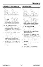
Page 88: ...ket and gradually lower the lift arm 4 When the bucket is full raise the bucket and tilt it back and back away from the material Loading a Bucket Fig 40 1 2 3 4 Loading a Bucket 1 Lower the bucket to the ground 2 Tilt the bucket slightly forward so the bucket cutting edge is pointing slightly down into the ground 3 Drive forward until the bucket is filled with material Adjust the bucket tilt as ne...

Page 89: ... the truck bed 2 Drive slowly forward and stop with the bucket over the inside of the truck 3 Tilt the bucket forward and dump the material into the truck bed 4 When the truck is half loaded use the bucket to spread the load evenly 5 Back away from the truck while tilting the bucket back and lowering the lift arm Tips When Loading Trucks Fig 42 Loading Trucks 1 The truck and machine working direct...

Page 90: ...bucket slightly and tilt it forward 2 Release material from the bucket while traveling forward 3 Tilt the bucket forward and adjust the lift arm height until the cutting edge is slightly above the ground 4 Drive in reverse smoothing the material released in step 2 with the front edge of the bucket Grading Using Float Fig 45 1 2 3 4 Grading Using Float 1 Lower the bucket to the ground 2 Activate th...

Page 91: ...erly secured on the fork arms Never leave a machine with the forks raised or a load unattended Make sure all persons stay clear of suspended loads DO NOT exceed pallet fork load center and or lifting capacity Refer to the pallet fork payload capacities table on page 83 Do not use high travel speed range when using pallet forks DO NOT use standard fork arms as reverse inverted forks Never allow a l...

Page 92: ...e immediately in front of the material 2 Position the fork arms parallel to the ground 3 Make sure the fork arms are adjusted as far apart as possible as allowed by the load and are both the same distance away from the center line of the load 4 Adjust the height of the fork arms to fit the lifting area at the bottom of the pallet 5 Drive slowly and carefully forward until the fork frame contacts t...

Page 93: ...ent Transport Position Carry materials 200 300 mm 8 12 above the ground and adjust as necessary to clear obstacles Generally carry the load as low as safely possible Tilt buckets back as shown in Fig 27 to prevent spilling material on page 75 22 Slightly tilt the pallet fork frame backwards Diesel Particulate Filter DPF Regeneration Procedures The Diesel Particulate Filter DPF treats exhaust emiss...

Page 94: ... page 91 Reset regeneration occurs automatically unless inhibited approximately every 100 hours of operation NOTE Reset regeneration effectiveness is improved if the machine is operated at mid to high throttle settings while regener ation is in progress Fig 46 Q F 1234 5 C E H Reset Regeneration In Progress When reset regeneration occurs the DPF in progress elevated temperature symbol Q Fig 46 dis...

Page 95: ...t screen will return 1 minute after being dismissed for as long as the request remains active IMPORTANT Perform stationary regeneration as soon as possible when the stationary regeneration request screen displays Postponing stationary regen eration for extended periods will cause significant reduction in engine power 50950436 H0521 and will force premature DPF filter core replacement Fig 49 n min ...

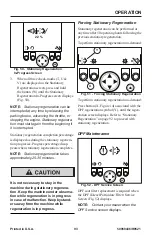
Page 96: ...s It is not necessary to stay in the machine during stationary regenera tion Keep the machine under observa tion while regeneration is in progress in case of malfunction Keep bystand ers away from the machine while regeneration is in progress Forcing Stationary Regeneration Stationary regeneration can be performed at any time after 50 operating hours following the previous stationary regeneration ...

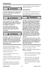
Page 97: ...ts and the engine compartment Take the keys with you Jump Starting If the battery becomes discharged or does not have enough power to start the engine use jumper cables and the following procedure to jump start the engine The ONLY safe method for jump start ing a discharged battery is for TWO PEOPLE to perform the following pro cedure The second person removes the jumper cables so that the operato...

Page 98: ...erate the machine or shut the engine off Lifting the Machine using a Crane Make sure the crane and the lifting gear cables chains have sufficient load bearing capacity The crane and the lifting gear must be adjusted to the proper dimensions Always lift the machine so it is horizon tal when it is raised Secure the machine against uninten tional movement Keep clear of suspended loads Never lift with...

Page 99: ...al that may reduce traction Move the machine on and off the vehicle ramp slowly and carefully Failure to follow these instructions could result in an overturn accident Towing the machine is not recom mended as a means of transportation Observe all local regulations governing the loading and transporting of equipment Reference U S Federal Motor Carrier Safety Regulations Section 392 Ensure that the...

Page 100: ...have sufficient capacity for the size and weight of the machine Refer to Specifications on page 37 Make sure the load does not fall short of the minimum axle load of the steering axle otherwise the transport vehicle s steering could be seriously affected Remove any mud snow or ice from the tracks on the machine to prevent slipping Position the machine at the lowest possible position on the transpo...

Page 101: ...amaged if the engine oil level is too low 2 Start the engine 50950436 G0121 3 Raise the hitch plate attachment enough so that it will not touch the loading ramps 4 Slowly and carefully drive the machine in reverse onto the transport vehicle with the bucket end facing down the ramp 5 Do not adjust travel direction while trav eling on the ramps Instead drive down off of the ramps and re align the ma...

Page 102: ...d follow the engine manufacturers recommendations from the Engine Operator s Manual 4 Start the engine Observe all gages If all gages are functioning properly and read ing normal move the machine outside 5 Once outside park the machine and let the engine idle for at least five minutes 6 Shut the engine off and walk around machine Make a visual inspection look ing for evidence of leaks Final Shutdo...

Page 103: ...es no dangers in the place where it is standing 12 Remove any dirt and or debris from the engine compartment the chassis and the cylinder rod surfaces 13 Remove the battery 14 Lock the cab door the storage compart ment the battery and hydraulic filler com partments and the engine compartment Remove the key s and take it them with you Machine Disposal Make sure all materials are disposed of in an e...

Page 104: ... manual for more information regarding recommended engine lubricants quantities required and grades System Type Type and Amount of Lubricant Hydraulic Use Petro Canada HVI60 Mobil DTE 15M or equivalent which con tain anti rust anti foam and anti oxidation additives and conforms to ISO VG46 Capacity 30 0 L 8 U S gallons Grease Fittings Use lithium based grease Engine Oil Conventional oils select th...

Page 105: ...n Points Wipe dirt from the fittings before and after applying grease to prevent contamination Replace any missing or damaged fittings Avoid excessive greasing to minimize dirt build up Fig 57 Grease Fitting On Hitch Pin Fig 58 Grease Fitting on Lift Arm Pivot ...

Page 106: ...Lubrication Printed in U S A 103 50950436 H0521 Fig 59 Grease Fittings on Lift Cylinder Rod End Fig 60 Grease Fitting on Lift Cylinder Base End ...

Page 107: ...0 Hours 250 Hours 1000 Hours or Annually Check Engine Oil Level X Check Hydraulic Oil Level X Grease Hitch Hitch related Cylinder Pivots and Latch Pins X Grease Lift Arm Pins X X Change Engine Oil X 500 hours Change travel motor gear oil X Change Hydraulic Oil X Check and Drain Water Separator X Change Coolant X Change travel motor gear oil every 2000 hours or with any drive motor repair ...

Page 108: ... Hours or Annually Change hydraulic oil filter X Change engine oil filter X Change cab air filter if applicable X Change outer air cleaner filter ele ment Check and change inner air cleaner element if necessary X Replace Filter in Water Separator X Change Main Fuel Filter X1 Change Water Separator Filter X 1 Non DPF machines require a 250 hour main fuel filter change ...

Page 109: ...50950436 H0521 106 Printed in U S A ...

Page 110: ...ine air cleaner restriction indicator X Check for loose or missing parts repair replace if necessary X Check engine oil level and condition X Check fuel level and fill if necessary Check hydraulic oil level and condition X Check coolant level and condition X Check cooling system system for dirt and debris X Check water separator drain water if present X Check windshield washer system and wiper bla...

Page 111: ... and hinges X Change outer air cleaner filter element Check and change inner air cleaner element X Change hydraulic reservoir oil X Drive motor front case oil X3 Change fuel filter X4 Change coolant X 1 After every 500 hours 2 Replace if needed 3 Change every 2000 hours or yearly 4 Non DPF machines require a 250 hour fuel filter change interval DPF machines require a 500 hour fuel filter change in...

Page 112: ...ick with a clean cloth and replace it in the engine Push it in until it is fully inserted 7 Remove the dipstick again The oil level should be within the Add and Full markings 8 Markings on the dipstick represent full and low add oil levels Refer to the Maintenance Interval Chart page 107 for the service interval for replacing the engine oil and filter IMPORTANT Do not over fill the engine with oil...

Page 113: ...s ft 11 Remove the oil cap and add the rec ommended oil Refer to Fuel System Maintenance on page 112 12 Start the engine and let it run for several minutes at low idle Stop the engine Check for leaks at the oil filter drain plug and remote oil drain hose Check the oil level Add oil if it is not at the top mark on the dipstick NOTE Oil capacity listed is approximate Always verify proper oil level w...

Page 114: ...dicator turns red The inner element should be replaced every third time the outer element is replaced unless the outer element is damaged or the inner element is dirty Along with a daily check of the restriction indicator check the air cleaner intake hose and clamps and the mounting bracket hardware to be sure they are properly tightened Fig 65 1 6 4 3 5 2 Dual Element Air Cleaner 1 Restriction In...

Page 115: ...triction indicator by pressing the reset button DPF Exhaust System Service DPF soot filter replacement is required when the DPF Service screen Fig 66 is shown on the multi purpose display Fig 66 DPF Service Screen NOTE DPF service should be per formed only by an authorized dealer Fuel System Maintenance Diesel fuel is flammable Keep the machine away from open flames Do not smoke when refueling or ...

Page 116: ...mpliance with fueling standards for proper grounding and bonding practices Though not necessary to leave locked the use of a locking fuel cap protects the loader from fuel theft or fuel system vandalism The key to this lockable fuel cap should be secured to the loader s key ring A torque override features aids in the proper installation of the fuel cap It produces an audible click as the o ring th...

Page 117: ...needs to be drained position a suitable collection container underneath the water separator drain b Turn the fuel shut off valve lever G on the water separator to the OFF position c Loosen drain plug H at the bottom of the water separator Allow water to drain until indicator ring falls to the bot tom of the cup 6 Prime the fuel system by turning the ignition key to the ON position without starting...

Page 118: ...lic fluid as required Replace the cap Changing Hydraulic Oil and Filter NOTE The hydraulic oil filter can be changed without changing the hydraulic oil or draining the hydraulic reservoir Change the hydraulic oil filter after 500 hours or 1 year of use thereafter Change the hydraulic oil if it becomes con taminated after major repairs and or after 500 hours or 1 year of use 1 Perform the Mandatory...

Page 119: ... Start the machine Cycle through all hydraulic functions several times to purge air from the hydraulic system Shut down the machine 12 Check the machine for hydraulic oil leaks Correct any leaks as required 50950436 G0121 13 Add oil to the hydraulic system as required until the level reaches the FULL marking on the dipstick Replace and tighten the hydraulic oil dipstick fill cap Engine Cooling Sys...

Page 120: ...et the system cool Remove the radiator cap only after the coolant has cooled Remove the cap slowly or severe burns may result 6 Remove the drain plug N Fig 73 and drain the coolant into a suitable container with a minimum capacity of 6 62 L 7 U S qts underneath the radiator 7 Replace the drain plug NOTE Protect the cooling system by adding premixed 50 water and 50 ethylene glycol and supplemental ...

Page 121: ...erces the skin Failure to obtain prompt medical assistance could result in gangrene or other seri ous damage to tissue Always relieve hydraulic system pres sure before performing any mainte nance on the machine Do not tighten leaking connections when the hydrau lic system is under pressure Never weld or solder damaged or leaking pressure tubes and or screw connections Always replace damaged hydrau...

Page 122: ...spect the tracks daily for damage and wear IMPORTANT To avoid damaging the tracks and to ensure maximum track life refer to Rubber Track Use Cautions and Tips on page 72 Observe the following conditions to extend track life Avoid traveling or turning on broken stone jagged rock metal or other material that could damage or cut the tracks Avoid traveling on riverbeds or areas with soft rocks that co...

Page 123: ...0950436 H0521 rear idler wheel at using a pry bar and your foot IMPORTANT Guides on the inside of the track must straddle the rear idler 8 Place a block under the new track to hold the track against the bottom of the rear idler wheel 9 Using a hoist with a hook and a pry bar lift guide the new track onto the drive sprocket IMPORTANT Lugs on the inside of the track must be fully engaged by drive sp...

Page 124: ...re using the machine Only use proper original equipment fuses with the specified current rating Turn off the machine immediately if there are any problems with the electri cal system Work on the machine s electrical system must be done only by a trained technician Battery Before servicing the battery or electri cal system disconnect the negative cable from the negative battery termi nal or if the ...

Page 125: ... cell battery To access the battery open the rear door and lift the engine cover The battery top must be kept clean Clean it with an alkaline solution ammonia or baking soda and water After foaming has stopped flush the battery top with clean water If the terminals and cable connection clamps are corroded or have a build up disconnect the cables and clean the terminals and clamps with the same alk...

Page 126: ...voir R Fig 80 is located inside the engine compartment Check the windshield washer reservoir level daily before starting the machine and fill if necessary IMPORTANT Fill the windshield washer fluid reservoir with clean tap water or wind shield washer fluid only If using tap water add a cleaning agent if required and or antifreeze in cold weather ...

Page 127: ...MAINTENANCE 50950436 H0521 124 Printed in U S A Maintenance Log Date Hours Service Procedure ...

Page 128: ...MAINTENANCE Printed in U S A 125 50950436 H0521 Maintenance Log Date Hours Service Procedure ...

Page 129: ...MAINTENANCE 50950436 H0521 126 Printed in U S A Maintenance Log Date Hours Service Procedure ...

Page 130: ...MAINTENANCE Printed in U S A 127 50950436 H0521 Maintenance Log Date Hours Service Procedure ...

Page 131: ...MAINTENANCE 50950436 H0521 128 Printed in U S A ...

Page 132: ...uel pump malfunction Check electrical connections voltage to fuel pump Contact dealer Engine turns over but will not start Engine cranking speed too slow Check battery and charge replace as necessary tighten battery terminals Fuel tank empty Fill tank and vent fuel system if necessary Fuel filter plugged or restricted Change fuel filter Fuel paraffin separation in winter Use winter grade diesel fu...

Page 133: ...ioned With engine off reposition shroud contact dealer Improper oil grade or oil excessively dirty Change engine oil Exhaust restricted Allow exhaust to cool remove restriction Air filter restricted Replace filter s Low coolant level Top off coolant Loose fan belt Tighten fan belt Dirty restricted radiator Clean radiator Thermostat malfunction Replace thermostat Exhaust excessively smoky Black smo...

Page 134: ...r auxiliary system continuously overloaded Improve operation procedure Drive motor s or hydrostatic pump internal damage leakage Contact dealer Oil cooler fins restricted Clean oil cooler fins Hydraulic oil filter restricted Replace filter Hydraulic oil filter Hydraulic oil filter maintenance required Replace hydraulic oil and filter NOTE During cold start in cold temperatures this indicator may b...

Page 135: ...r replace with proper viscosity oil Hydraulic oil level is too low Check oil level in reservoir If oil is low check for an external leakage Repair and add oil Solenoid valve s malfunctioning Check electrical connections to lift tilt solenoid and repair Restraint bar or seat switch malfunction Check switches Auxiliary hydraulics do not function Restraint bar is raised Lower the restraint bar Lock s...

Page 136: ...act your dealer Air in the hydraulic system Cycle lift tilt cylinders to maximum stroke and maintain pressure for a short time to clear air from system Oil in hydraulic reservoir is low Check and add oil Bucket drifts downward with tilt control in neutral Oil leaking past tilt cylinder seals internal or external Contact your dealer Self leveling valve is malfunctioning Contact your dealer Leaking ...

Page 137: ... Lift spool in control valve not actuated or leaking Contact your dealer Lift arm doesn t main tain raised position with lift control in neutral Oil leaking past lift cylinder seals internal or external Contact your dealer Oil leaking past lift spool in control valve Contact your dealer Self leveling valve malfunctioning Contact your dealer Leaking hydraulic hoses tubes or fittings between control...

Page 138: ... relief valve s are malfunctioning Contact your dealer Sluggish response to acceleration Air in hydraulic system Cycle lift and tilt cylinders to maximum stroke and maintain pressure for a short time to clear air from system Also check for low oil level in the reservoir fill as needed Automatic parking brake is partially engaged Contact your dealer Hydraulic oil supply is too low Check for low oil...

Page 139: ...missing Contact your dealer Relief valves on rear hydrostatic pump malfunctioning Contact your dealer Control rod linkage to rear hydrostatic pump disconnected Attach control rod linkage Right side doesn t drive in one direction Relief valve on rear hydrostatic pump is malfunctioning Contact your dealer Rear hydrostatic pump malfunctioning Contact your dealer Left side doesn t drive in either dire...

Page 140: ...arness connectors at rear of ROPS FOPS not properly plugged in Check main harness connectors Reconnect repair as needed Starter does not engage when ignition key switch turned to its START position Poor electrical connections in start circuit Check connections repair as necessary Battery terminals cables loose corroded Clean battery terminals and cables and tighten Starter relay malfunction Test r...

Page 141: ...ections Alternator malfunction Repair replace alternator Hour meter malfunction Replace information center electronic display Work road lights inoperative Single light not working light bulb burned out faulty wiring Check and replace light bulb as needed check wiring connections No lights blown fuse Check circuit and replace fuse Light switch malfunction poor ground or other wiring connection Chec...

Page 142: ...Troubleshooting Printed in U S A 139 50950436 H0521 Error Codes ...

Page 143: ...Troubleshooting 50950436 H0521 140 Printed in U S A ...

Page 144: ...Troubleshooting Printed in U S A 141 50950436 H0521 ...

Page 145: ...Troubleshooting 50950436 H0521 142 Printed in U S A ...

Page 146: ...Troubleshooting Printed in U S A 143 50950436 H0521 ...

Page 147: ...rror 173 10 P1677 Exhaust Temp Sensor Malfunction Aftertreatment Error 412 10 P1675 EGR Gas Temp Sensor Malfunction Aftertreatment Error 1209 10 P1679 EGR High Pres Sensor Malfunction Aftertreatment Error 3242 10 P167E DPF Inlet Temp Sensor Malfunction Aftertreatment Error 3250 10 P167A DPF Intermediate Temp Sensor Malfunction Aftertreatment Error 3609 10 P167C DPF High Pres Sensor Malfunction Aft...

Page 148: ...ent and Actions 10 L Lubrication 101 Filter Table 101 Lubricant Capacities 101 Lubrication Points 102 Lubrication Schedule Intervals 104 Types of Lubricants 101 Index D Decals 27 ANSI Style Decals 29 Common Decals 28 Decal Locations 27 General Information 27 ISO Style Decals 33 New Decal Application 27 I Indicators and Controls 47 Battery Disconnect Switch 59 Beacon Option 59 Cab Heat Option 58 Di...

Page 149: ...ng a Booster Battery Jump Starting 118 Battery 121 Changing Engine Oil and Filter 109 Water Separator Inspection Maintenance 113 Windshield Washer Reservoir 123 O and Filter 115 OPERATION 61 After Operation 94 After Starting 65 Auxiliary Hydraulics Operation 82 Backfilling Holes and Embankments 86 Back up Alarm 72 Before Disposal 99 Before Operation 62 Cooling System 117 Cab Entry and Exit 62 Cold...

Page 150: ...arking Brake 63 Powering Attachments with Hydraulic Function 80 Removing Machine from Storage 99 Reset Regeneration 91 Engine Warm Up 65 Reset Regeneration Inhibit 91 Rubber Track Use Cautions and Tips 72 Decommissioning 99 Run In Period 66 Safety Interlock Float Control 79 System Hydraloc 66 Seat Belt 62 Regeneration 93 Self L eveling Option 79 Setting Down Loads Using Pallet Forks 90 Sprocket To...

Page 151: ...gnal Words 15 Signal Words 15 Specifications 37 Common Materials and Densities 45 Coolant Compound Table 40 Dimensions 38 Engine 40 Fluids Lubricants Types and Capacities 37 Hydraulic System 42 Payloads Capacities 39 Sound Power Pressure Levels 42 Standard and Optional Features 44 Tracks 40 Vibration Levels 43 Weights 40 T Troubleshooting 129 Electrical Troubleshooting 137 Engine Troubleshooting 1...

Page 152: ... 5 35 26 45 33 26 35 35 26 14 mm 0 6 in M16X1 5 45 33 55 41 40 30 50 37 16 mm 0 6 in M18X1 5 55 41 70 52 45 33 70 52 18 mm 0 7 in M22X1 5 65 48 125 92 60 44 125 92 22 mm 0 9 in M27X2 0 90 66 180 133 100 74 145 107 27 mm 1 0 in M33X2 0 150 111 310 229 160 118 210 155 33 mm 1 3 in M42X2 0 240 177 450 332 210 155 360 266 42 mm 1 7 in M48X2 0 290 214 540 398 260 192 540 398 48 mm 1 9 in G1 8A 9 7 13 1...

Page 153: ...52 18 mm 0 7 in M20X1 5 55 41 125 92 80 59 100 74 20 mm 0 8 in M22X1 5 65 48 135 100 100 74 125 92 22 mm 0 9 in M27X2 0 90 66 180 133 170 125 135 100 27 mm 1 0 in M33X2 0 150 111 310 229 310 229 210 155 33 mm 1 3 in M42X2 0 240 177 450 332 330 243 360 266 42 mm 1 7 in M48X2 0 290 214 540 398 420 310 540 398 48 mm 1 9 in G1 8A 35 26 55 41 45 33 45 33 13 16 mm 0 5 in G1 4A 45 33 80 59 60 44 60 44 16...

Page 154: ...80 1092 1770 1305 870 642 1250 922 M30 1420 1047 2010 1482 2400 1770 1200 885 1700 1254 With fine pitch thread All torque values are in Nm lb ft unless marked otherwise Thread Threads according to DIN 912 DIN 931 DIN 933 etc Threads according to DIN 7984 8 8 10 9 12 9 8 8 10 9 M8X1 0 25 18 37 27 32 43 22 16 32 24 M10X1 0 50 37 75 55 88 65 43 32 65 48 M10X1 25 49 36 71 52 83 61 42 31 62 46 M12X1 25...

Page 155: ...50950436 H0521 152 Printed in U S A ...

Page 156: ...Manitou Group One Gehl Way West Bend WI 53095 0179 U S A www us manitou com www mustangmfg com 2021 All rights reserved For Support and Service Contact Your Dealer ...

Reviews: