MAINTENANCE
120
Printed in U.S.A.
1 .
With the machine running and the drive
system not moving, remove tension cyl-
inder stop (K, Fig . 76) on the side on the
machine with the track to be replaced .
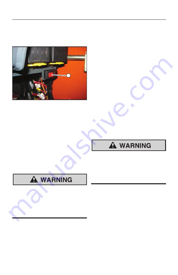
Fig. 77 -
P
Track Tension Switch
2 .
With the machine running and the drive
system not moving, open the engine
compartment . Press and hold the red lock
button (P, Fig . 77) on the track tension
service switch, press the switch to set the
track tension cylinders into the service
(retracted) position .
3 .
When the track tension cylinders are in
the service (retracted) position, shut off
the machine .
4 .
Raise the machine about 150 mm (6 .0”)
so the tracks are free to move .
Use solid support blocking. Never rely
on jacks or other inadequate supports
when maintenance work is being done.
Never work under any equipment sup-
ported only by jacks.
5 .
Use a pry bar to pry/guide the old track at
off the front idler wheel.
6 .
Using a hoist with a hook installed and a
pry bar, lift/guide the old track off at the
drive sprocket . Remove the old track .
7 . Using a hoist with a hook, lift the new
track and maneuver the track under the
50950436
/
H0521
rear idler wheel at using a pry bar and
your foot .
IMPORTANT:
Guides on the inside of
the track must straddle the rear idler.
8 .
Place a block under the new track to hold
the track against the bottom of the rear
idler wheel .
9 .
Using a hoist with a hook and a pry bar,
lift/ guide the new track onto the drive
sprocket .
IMPORTANT:
Lugs on the inside of
the track must be fully engaged by drive
sprocket.
Using a pry bar and wedging blocks, pull/
guide the new track over the front idler wheel
and under the bottom rollers . Carefully, direct
an assistant to start the machine and direct
the assistant to operate the track drive slowly
forward/back to work the track over the front
idler wheel .
Keeps hands and feet clear from
between the track and the idler/
roller wheels when installing tracks.
Crushing of body parts and amputation
can result.
NOTE:
The tie-down bracket can be
used as a lever point for prying the track
into place over the front idler wheel.
IMPORTANT:
Guides on the inside of
the track must straddle the front idler and
bottom roller wheels.
10 . Be sure the new track is fully engaged
around the idler and roller wheels, and in
the drive sprocket, all the way around .
11 . Remove any wedging blocks that were
used to guide the track .
12 . Remove the block placed under the track .
Summary of Contents for MUSTANG 1050RT
Page 63: ...Indicators and Controls 50950436 H0521 60 Printed in U S A ...
Page 109: ...50950436 H0521 106 Printed in U S A ...
Page 127: ...MAINTENANCE 50950436 H0521 124 Printed in U S A Maintenance Log Date Hours Service Procedure ...
Page 128: ...MAINTENANCE Printed in U S A 125 50950436 H0521 Maintenance Log Date Hours Service Procedure ...
Page 129: ...MAINTENANCE 50950436 H0521 126 Printed in U S A Maintenance Log Date Hours Service Procedure ...
Page 130: ...MAINTENANCE Printed in U S A 127 50950436 H0521 Maintenance Log Date Hours Service Procedure ...
Page 131: ...MAINTENANCE 50950436 H0521 128 Printed in U S A ...
Page 142: ...Troubleshooting Printed in U S A 139 50950436 H0521 Error Codes ...
Page 143: ...Troubleshooting 50950436 H0521 140 Printed in U S A ...
Page 144: ...Troubleshooting Printed in U S A 141 50950436 H0521 ...
Page 145: ...Troubleshooting 50950436 H0521 142 Printed in U S A ...
Page 146: ...Troubleshooting Printed in U S A 143 50950436 H0521 ...


