background image

3-4

IT

EN

648870 IT

-EN-NL (04/05/2015)

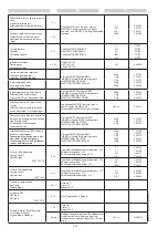
LISTA DELLE OPERAZIONI DA 

EFFETTUARE PER IL:

1° TAGLIANDO OBBLIGATORIO

REVISIONE OBBLIGATORIA ENTRO 100 ORE 

. Questa revisione deve essere obbligatoria-

mente effettuata entro le prime 100 ore dalla 

messa in servizio della macchina (entro il 

primo termine raggiunto).

SCATOLA CAMBIO

- Sostituzione olio scatola cambio

- Pulizia sensore di velocità

REVISIONE OBBLIGATORIA ENTRO 500 ORE 

O 6 MESI. Questa revisione deve essere obbli-

gatoriamente effettuata entro le prime 500 

ore o entro 6 mesi dalla messa in servizio 

della macchina (entro il primo termine rag-

giunto).

MOTORE TERMICO

-Sostituzione olio

-Cambio filtro olio

-Cambio filtri combustibile

-Pulizia filtro aria

-Controllo tenute: iniezione alimentazione 

-Controllo circuito raffreddamento

-Controllo tensione cinghia

-Registrazione valvole

TRASMISSIONE IDROSTATICA

-Cambio filtro aspirazione

-Pulizia filtro ritorno (secondo montaggio)

-Controllo livello olio

-Controllo registrazione comando taglio tras-

missione

PONTI / SCATOLA CAMBIO

-Sostituzione olio differenziale / carter freni

-Sostituzione olio riduttori

-Ingrassaggio perni, articolazioni e comandi

-Ingrassaggio oscillazione

-Sostituzione olio scatola cambio

- Pulizia sensore di velocità

CIRCUITO IDRAULICO

-Cambio filtro ritorno

-Controllo livello olio

-Controllo tenute

CIRCUITO DI FRENATURA

-Controllo funzionamento del

 freno di servizio e parcheggio 

-Controllo livello liquido del freni

 (secondo montaggio)

LISTS OF THE OPERATION TO BE 

CARRIED OUT FOR THE FIRST COUPON:

1st COUPON OBLIGATORY

MANDATORY 100 HOUR SERVICE. This ser-

vice must be carried out after approximately 

the first 100 hours of operation following the 

start-up of the machine (whichever occurs 

first).

GEARBOX

-Changing oil gearbox

- Speed sensor cleaning

MANDATORY 500 HOUR OR 6 MONTH 

SERVICE. This service must be carried out 

after approximately the first 500 hours of 

operation or within the 6 months following 

the start-up of the machine (whichever 

occurs first).

ENGINE

-Change engine oil

-Change engine oil filter

-Change fuel filter

-Clean air filter

-Tightness check: injection power supply

-Check cooling circuit

-Check belt(s) tension

-Valve clearance

HYDROSTATIC TRANSMISSION

-Change suction filter 

-Clean Return filter (as for assembly)

-Check oil level 

-Check transmission inching control 

 adjustment

AXLES / GEAR BOX

-Change differential / brake housing

-Change oil of reduction gears

-Lubrification of pivots, hinges 

 and controls

-Oscilation lubrification

-Change transfer box oil

-Changing oil gearbox  

- Speed sensor cleaning

HYDRAULIC CIRCUIT

-Change return filter(s)

-Check oil level

-Check tightness 

BREAKING CIRCUIT

-Check service brake operation

-Check brake fluid level (as for 

 assembly)

NL

LIJST MET HANDELINGEN DIE 

UITGEVOERD MOETEN WORDEN VOOR:

1ste VERPLICHTE KEURING

VERPLICHTE REVISIE NA 100 UREN. Deze 

revisie moet verplicht worden uitgevoerd 

binnen de eerste 100 bedrijfsuren na de 

inbedrijfstelling van de machine (wanneer 

de eerste termijn wordt bereikt).

VERSNELLINGSBAK

- Olie versnellingsbak verversen

- Snelheidssensor reinigen

VERPLICHTE REVISIE NA 500 UREN OF 6 

MAANDEN. Deze revisie moet verplicht 

worden uitgevoerd na ongeveer 500 

bedrijfsuren of 6 maanden na de inbe-

drijfstelling van de machine (wat het eerst 

wordt bereikt).

VERBRANDINGSMOTOR

-Olie verversen

-Oliefilter vervangen

-Brandstoffilters vervangen

-Luchtfilter reinigen

-Controle afdichtingen: inspuiting 

-Controle koelcircuit

-Controle riemspanning

-Aftelling kleppen

HYDROSTATISCHE TRANSMISSIE

-Aanzuigfilter vervangen

-Retourfilter reinigen (volgens montage)

-Controle oliepeil

-Controle afstelling bedieningselementen 

voor uitschakelen transmissie

BRUGGEN / VERSNELLINGSBAK

-Olie differentieel / remcarter vervangen

-Olie vertragingen verversen

-Pennen, geledingen en bedieningselemen-

ten invetten

-Oscillatie invetten

-Olie versnellingsbak verversen

- Snelheidssensor reinigen

HYDRAULISCH CIRCUIT

-Retourfilter vervangen

-Controle oliepeil

-Controle afdichtingen

REMCIRCUIT

-Controle van de werking van de voetrem 

en de handrem

-Controle van het vloeistofniveau van de 

remmen (volgens montage)

Summary of Contents for PRIVILEGE MRT 3255 PLU

Page 1: ...DERSTOOD BY OPERATORS DEZE HANDLEIDING MOET ALTIJD IN DE HEFTRUCK BLIJVEN EN MOET DOOR DE BESTUURDERS HELEMAAL GELEZEN EN BEGREPEN WORDEN MANITOU ITALIA S r l Via Cristoforo Colombo 2 Localit Cavazzon...

Page 2: ......

Page 3: ...nical modifications an on going process the aim of which is to offer products which are being continually improved and the latest up date of the manual we must point out for the sake of correctness th...

Page 4: ......

Page 5: ......

Page 6: ......

Page 7: ...1 ISTRUZIONI E NORME DI SICUREZZA SAFETY INSTRUCTIONS AND REGULATIONS AANWIJZINGEN EN VEILIGHEIDSVOORSCHRIFTEN...

Page 8: ......

Page 9: ...s onderdelen inkoopt doet dit op eigen risico De gebruiker die de heftruck wijzigt of door derden laat wijzigen moet er rekening mee houden dat hij een nieuwe uitrusting op de markt brengt en dat hij...

Page 10: ...e beste technologische capaciteiten voor het onderhoud van de heftruck De originele reserveonderdelen worden uitsluitend door MANITOU en zijn netwerk van dealers verspreid De lijst van het netwerk van...

Page 11: ...heftruck niet in gevaar brengt De fabrikant is uiteraard niet in staat alle risicosituaties te voorzien Dientengevolge zijn de instructies en de veiligheidsvoorschriften van de heftruck die door de fa...

Page 12: ...uitvoering van een taak Bij bepaalde machines het voorspelbare gedrag van bepaalde personen zoals leerlingen jeugd personen met een handicap personeel in opleiding Heftruckbestuurders die om persoonl...

Page 13: ...rond zetten en de parkeerrem aantrekken Nooit de contactsleutel op de heftruck achterlaten als de bestuurder niet aanwezig is Nooit een geladen heftruck laten staan op een helling van meer dan 15 zelf...

Page 14: ...s niet bevoegd iemand anders toestemming te geven de heftruck te besturen De heftruck moet vakkundig gebruikt worden C Gewoon onderhoud Als de gebruiker merkt dat zijn heftruck niet in goede staat van...

Page 15: ...emming is het verplicht de heftruck regelmatig te laten controleren De periodiciteit van deze controlebeurten is bepaald in de wetgeving van het land waar de heftruck gebruikt wordt Het onderhoud en d...

Page 16: ...Protection against frost See chapter LUBRICANTS AND FUEL in paragraph 3 MAINTENANCE Adaptation of lubricants Ask your dealer for information Engine filtration Lighting Working headlight Optional solu...

Page 17: ...In het geval de bedieningsorganen voorzien zijn van een geforceerde werking blokkering van de hendel is het verboden de bestuurdersplaats te verlaten voordat deze bedieningsorganen in de neutrale stan...

Page 18: ...ijn vrij staat Draai de contactsleutel in stand I voor het elektrische contact Controleer het brandstofpeil op de verklikker De contactsleutel in stand II draaien om de voorverwarming in werking te st...

Page 19: ...onder controle houden Langzaam rijden op vochtige glibberige of onregelmatige grond Geleidelijk aan en zonder stoten remmen De omkeerinrichting van de heftruck alleen gebruiken als de heftruck stil st...

Page 20: ...et een last mag in geen geval de 10 km h overschrijden Aanwijzingen voor het rijden Het oliepeil van de transmissie controleren De vorken of het werktuig in de transportstand zetten d w z ongeveer 300...

Page 21: ...ls de bestuurder de bestuurdersplaats moet verlaten ook al is het maar even de handrem aantrekken en de hendel van de omkeerschakeling in zijn vrij zetten Controleren of de heftruck niet op een plaats...

Page 22: ...zijn er optionele oplossingen beschikbaar Raadpleeg uw agent of dealer voor nadere informatie Het vervoer van ladingen op de openbare weg is verboden en de op de heftruck gemonteerde werktuigen moete...

Page 23: ...er de machine met het chassis parallel aan de grond met behulp van de hellingsregelaar De stabilisatoren opheffen en zo ver mogelijk intrekken De pen ter blokkering van het draaien aanbrengen Sluit de...

Page 24: ...dekken De beschermingen op de gemonteerde werktuigen aanbrengen Plaats indien nodig het blokkeringsafstandstuk op de hef en kantelcilinder De werktuigen aan de voorkant worden aan de drie zijden aange...

Page 25: ...leren of het werktuig goed gemonteerd is en op zijn steun is vastgezet Controleren of het veiligheidssysteem in de cabine in overeenstemming met het gemonteerde werktuig is ingesteld De limieten van h...

Page 26: ...controleren of de veiligheidsregels op de bouwplaats overeenkomen met de plaatselijke van kracht zijnde regels mbt alle werkzaamheden in de buurt van elektrische leidingen Niemand toestemming geven in...

Page 27: ...op de omgeving u de heftruck alleen mag verplaatsen als de arm in de transportstand staat De heftruck alleen in uitzonderlijke gevallen manoeuvreren met de arm in opgeheven stand dan de uiterste voorz...

Page 28: ...n goed zicht op het traject heeft alvorens de arm op te tillen en de heftruck te gebruiken Als u niet voldoende zicht heeft als u met een last vooruit rijdt rijd dan achteruit Dit mag alleen in uitzon...

Page 29: ...ravit pi distante rivolgetevi al vostro agente o concessionario Per i carichi irregolari determinare il centro di gravit nel senso trasversale prima di ogni movimentazione Fig B Per i carichi con cent...

Page 30: ...it van de lading te garanderen Langzaam de heftruck vooruit rijden 1 en de vorken tegen de lading aan zetten Fig E zo nodig de arm 2 iets optillen bij het beetpakken van de lading Trek de handrem aan...

Page 31: ...aragraaf E ZICHT in hoofdstuk AANWIJZINGEN VOOR DE VERPLAATSING met betrekking tot de zichtbaarheid op het traject Niet vergeten dat er een bepaalde afstand nodig is tussen de stapel en de heftruck om...

Page 32: ...back the lift truck up Fig K Manoeuvring very gently and carefully See paragraph E VISIBILITY in the chapter HANDLING INSTRUCTIONS for visibility of the road back up the lift truck 1 to release the lo...

Page 33: ...beurtelings in te trekken en op te tillen 3 Fig N of indien mogelijk door de heftruck achteruit te rijden 3 zie paragraaf E ZICHT in hoofdstuk AANWIJZINGEN VOOR DE VERPLAATSING met betrekking tot het...

Page 34: ...e horizontale stand op de waterpas controleren voor de arm op te heffen zie hoofdstuk CONTROLE EN BEDIENINGSORGANEN in deel 2 BESCHRIJVING Niet alleen de dwarse helling van het terrein be nvloedt de h...

Page 35: ...sse dalle normative europee in vigore al momento dell immissione nel mercato Funzioni di sicurezza I radiocomandi sono dotati di alcune funzioni che permettono di fornire un elevato livello di sicurez...

Page 36: ...si svolgono nel luogo di lavoro Non avviare o utilizzare mai l unit trasmittente in situazioni lavorative in cui si possa perdere l equilibrio o si possa inciampare Verifica sempre il corretto funzio...

Page 37: ...eve esser trasportato e conservato all intero del suo imballo originale fino a quando non viene installato sulla macchina installazione l installazione ed il collaudo del radioco mando devon esser ese...

Page 38: ...ttente 2 data di acquisto riportata sul certificato di garanzia 3 anomalia riscontrata 4 indirizzo e numero di telefono del luogo in cui utilizzato e il nome del responsabile da contattare Vedere Capi...

Page 39: ...l operatore le informazioni e o le segnalazioni riguardanti la macchina che sta comandando Durante il normale funzionamento del radiocomando prestare attenzione alle indicazioni visualizzate e segnala...

Page 40: ...batterij moet vervangen worden door een volle Niet gebruik van de zender Als de zender gedurende de tijd van het automatisch uitgaan aan blijft zonder dat er besturingen geactiveerd zijn dan gaat hij...

Page 41: ...zijn aangebracht kan gevaarlijk zijn Een stabiliseerklep mag alleen gedemonteerd worden als de betreffende cilinder niet in werking is en als er geen druk staat op het hydraulische circuit Deze hande...

Page 42: ...inder plaatsen en blokkeren met de pen 2 en de splitpen 3 De telescopische arm langzaam laten zakken en dan de hydraulische bewegingen onderbreken voor tegen de wig te stoten DEMONTAGE VAN DE WIG De t...

Page 43: ...plaatsen D Wassen De heftruck of op zijn minst de betreffende zone wassen voor iedere ingreep Vergeet niet het portier en de achterruit van de cabine te sluiten Tijdens het wassen de geledingen de el...

Page 44: ...oad on the tyres Stop the engine and remove the ignition key from the dashboard Always lock the cab doors and all machine access hatches Clean the machine in general Completely change all lubricants a...

Page 45: ...pressure Clean the machine to remove the protective grease Check all lubricant levels and top up if necessary Change the combustion air filter Grease all components fitted with grease nipples Start th...

Page 46: ...r de volgende controles te hebben verricht Invetten De verschillende smeerpunten en oliepeilen controleren zie hoofdstuk ONDERHOUDSTIJDEN in deel 3 ONDERHOUD en eventueel bijvullen De smeermiddelen wo...

Page 47: ...dstuk KENMERKEN in het deel 2 BESCHRIJVING Voedingscircuit van de brandstof Controleren of de slangen en buizen goed afgedicht zijn Indien nodig het brandstoffilter en het voedingssysteem legen Elektr...

Page 48: ...cco rotazione non sia inserito vedere punti 3 del capitolo STRUMENTI DI CONTROLLO E DI COMANDO Attenersi ai dati indicati sui diagrammi di carico Verificare che i cofani e la portiera inferiore siano...

Page 49: ...en approved for operation with the four outriggers partially extended and completey extended Never operate with the truck on 1 2 or 3 outriggers Level the truck with the outriggers before lifting the...

Page 50: ...can be stabilized by positioning a platform wider than the foot under each stabilizer for better distribution of the pressure at the ground and to reduce possible sinking of the stabilizer foot Before...

Page 51: ...2 DESCRIZIONE DESCRIPTION BESCHRIJVING...

Page 52: ......

Page 53: ...C C C C D D D D D D D DE E E E E E E EC C C C C C C CL L L L L L L LA A A A A A A AR R R R R R R RA A A A A A A AT T T A AT A AT T T T TI I I I I I I IO O O O O O O ON N N N N N N N O O O O O O O OF...

Page 54: ...nginio gamintojas 6 Parei kia kad is renginys 7 Atitinka toliau nurodytas direktyvas ir nacionalinius teis s aktus perkeltas j nuostatas 8 IV priedas d l ma in 9 Sertifikato Nr 10 Paskelbtoji staiga 1...

Page 55: ...FTTRUCKMANUFACTURER SPLATE A 1 MODEL 2 SERIES 3 Year of manufacture 4 Model year 5 Serial No 6 ISO TR 14396 Power 7 Mass without load 8 Authorised Total Circulating Weight 9 Nominal capacity 10 Tracti...

Page 56: ...icematerialedell unit assialeapistoni 13 Codice di ordinazione MOTREIDROSTATICO D 1 Produttore 2 Designazione pianta interna 3 Categoria opzionale 4 Sensodirotazione vistasull alberomotore qui in sens...

Page 57: ...di serie 3 Riferimento MANITOU ASSALEPOSTERIORE F 1 Tipo indice di modifica 2 N di serie 3 Riferimento MANITOU CABINA G 1 Tipo indice di modifica 2 N di serie TARGHETTACOSTRUTTOREDELL ACCESSORIO H 1...

Page 58: ...600 rpm 900 Nm a 1200 1600 rpm Tipo di attacco principale SAE3 SAE3 PTO per servizio aggiuntivo tipo coppia max Post trattamento gas di scarico Sistema SCR silenziatore di scari co con catalizzatore i...

Page 59: ...alternatore CIRCUITO IDRAULICO Pompa idrostatica Tipo di pompa A4VG145 Pompa variabile a pistoni assiali Rexroth Cilindrata max litri cm3 0 1453 145 3 Portata a 2200 rpm l min 313 Pressione bar psi 4...

Page 60: ...in configurazione standard su terreno piano eccetto condizioni particolari MRT X 3255 MRT 3255 Velocit di marcia Avanti a vuoto km h mph 40 24 85 Indietro a vuoto km h mph 25 15 53 Capacit di sollevam...

Page 61: ...loccaggio Impianto idraulico Stabilizzatori Tipo Telescopici a 3 elementi Nb 4 Comando Comando individuale o simultaneo CAPACIT LIQUIDI Capacit dei serbatoi Olio idraulico e di trasmissione Litri 297...

Page 62: ...Nm 1200 1600 rpm Main Coupling type SAE3 SAE3 Additional service PTO type max torque Exhaust Gas Aftertreatment SCR system exhaust muffler with catalyst AdBlue injection with supplying and metering un...

Page 63: ...iable pump Rexroth Displacement max liters cm3 0 1453 145 3 Flow rate 2200 rpm l min 313 Pressure bar psi 490 7106 849 Hydraulic circuit main pump Pump Type A11VO95 Axial piston variable pump Rexroth...

Page 64: ...cular conditions MRT X 3255 MRT 3255 Driving Speed Forward unloaded km h mph 40 24 85 Reverse unloaded km h mph 25 15 53 Lifting Capacity Standard lifting height m ft 31 6 103 67 Lifting heigt at max...

Page 65: ...ype Hydraulic system Outriggers Type Telescopic 3 elements Nb 4 Control Individual or simultaneous control LIQUID CAPACITIES Tanks capacities Hydraulic and Transmission Oil Liters 297 Diesel Fuel Lite...

Page 66: ...ax koppel 705 Nm 1200 1600 rpm 900 Nm 1200 1600 rpm Type hoofdaansluiting SAE3 PTO per bijkomende dienst type max koppel Nabehandeling uitstoot SCR systeem uitstootdemper met katalysator injectie AdBl...

Page 67: ...de wisselstroomdynamo HYDRAULISCH CIRCUIT Hydrostatische pomp Type pomp A4VG145 Variabele axiale zuigerpomp Rexroth Max cilinderinhoud liter cm3 0 1453 145 3 Bereik aan 2200 rpm l min 313 Druk bar psi...

Page 68: ...scopische hefboom in standaardconfiguratie op een vlakke ondergrond uitgezonderd bijzondere omstandigheden MRT X 3255 MRT 3255 Rijsnelheid Vooruit onbelast km h mph 40 24 85 Achteruit zonder last km h...

Page 69: ...ydraulisch circuit Stabilisatoren Type Telescopisch met 3 elementen Nb 4 Bediening Afzonderlijke of gelijktijdige bediening CAPACITEIT VLOEISTOFFEN Capaciteit van de tanks Hydraulische en transmissie...

Page 70: ...118 19 J 3205 126 18 J1 3306 130 16 K 3803 149 72 K1 519 20 43 L 2064 81 26 M 2499 98 39 N 6490 255 51 O 7100 279 53 P 350 13 78 P2 14 P3 20 P4 20 Q 5560 218 90 R 4690 184 65 S1 5945 234 06 S2 6490 2...

Page 71: ...870 IT EN NL 04 05 2015 Load chart Operating Mode ONSTABILISERSWITHFORKSCARRIAGE Diagrammadicarico Modalit dilavoro SUSTABILIZZATORICONPORTAFORCHE NL Belastingsdiagram Werkingsmodus OPSTABILISATORENME...

Page 72: ...2 IT EN 648870 IT EN NL 04 05 2015 Load chart Operating Mode ON WHEELS TURRET ROTATED Diagrammadicarico Modalit dilavoro SUGOMME TORRETTARUOTATA NL Belastingsdiagram Werkingsmodus OPWIELEN TORENGEDRAA...

Page 73: ...EN 648870 IT EN NL 04 05 2015 Load chart Operating Mode ON WHEELS FRONT TURRET Diagrammadicarico Modalit dilavoro SURUOTE TORRETTAINPOSIZIONE FRONTALE NL Belastingsdiagram Werkingsmodus OPWIELEN VOORK...

Page 74: ...N 648870 IT EN NL 04 05 2015 COMANDI E DISPLAY CONTROLS AND DISPLAYS 18 13 11 3 10 9 4 8 28 12 23 21 23 1 17 15 19 14 6 8 25 26 5 29 32 33 34 34 34 35 35 35 35 22 35 37 14 20 27 36 A NL BEDIENINGEN EN...

Page 75: ...Control Lever For Lifting Lh Arm Rest Of Seat 23 Electrohydraulic Servocontrols Propor tional 24 Functions Charts 25 Optional Exclusion Control Switch 26 Selector For Movements Of Accessories And Pla...

Page 76: ...also be inclined upwards forwards by 13 Adjusting the seat height Pull lever upwards C 1 Position the seat at the required height Release the lever and make sure it returns to the blocking position Ad...

Page 77: ...seat belt is not twisted Wear the belt at the hip Fasten the safety belt and check to make sure it is locked properly Adjust the belt according to your body avoid pressing against the hip and avoid ex...

Page 78: ...ector J RH front stabilizer selector K LH rear stabilizer selector L RH rear stabilizer selector M Stabilizers movement selector N Stabilizers movements control O Hydraulic pivot switch P Steering typ...

Page 79: ...cestello 3 1 B INTERRUTTORE RADIO COMANDO Interruttore B 3 1 a due posizioni 1 2 3 1 premendo su 1 3 1 il radiocomando viene disabilitato premendo su 2 3 1 il radiocoman do viene abilitato e si illumi...

Page 80: ...the vehicle with respect to the ground hThe suspensions only work if the boom is retracted comple tely and the turret rotation blocking pivot is activated With the suspensions ac tive the manipulator...

Page 81: ...n the control panel lights up In cyclic mode press and re press pushbutton D 3 3 to select the requi red machine setup suspensions halfway or completely lowered E SUSPENSIONS SETUP CONTROL Press pushb...

Page 82: ...vehicle perfectly horizontal check the level gauge green bubble machine leveled 1 3 4a red bubble machine is not leveled 2 3 4a rAdjust the vehicle s slope lon gitudinally only if necessary moving th...

Page 83: ...andler is less than under 3 km h 1 86 mph or the machine is stopped The automatic safety brake is disabled if the gear switch is engaged and the rpm are accele rated by pressing on the gas pedal H CRU...

Page 84: ...ift or lower M1 3 5 Position M2 the outriggers extend or retract M2 3 5 Consult the next paragraph when carrying out the required operations N OUTRIGGER UP DOWN EXTENSION RETRACTION CONTROL After sele...

Page 85: ...ruck and turret rotation pin is deactivated 1 3 6a 3 yellowindicatorlightOn turretalmost aligned with the truck and the turret rotation pivot is deactivated 2 3 6a 4 greenindicatorlightOn turretaligne...

Page 86: ...7 and with safety block 2 3 7 To authorize movement the operator must turn switch Q 3 7 to position 1 3 7 and a red indicator lights up on the control panel 1 3 7a To reset the movement Safety system...

Page 87: ...more details e Baskets use manual PUSHBUTTON FOR RESTORING ELEC TRIC POWER SUPPLY FROM BATTERY AND ALLOWING I C ENGINE RESTART Only with platform If the emergency stop button is pressed from the bask...

Page 88: ...operator and the forklift truck are exposed to risks and there is nothing to prevent over load and or overturning of the vehicle Key selector To disable the Safety System the operator must turn 1 1 3...

Page 89: ...co del mezzo Nota Quando si disabilita il sistema di sicu rezza automaticamente si attivano una spia rossa su display 1 7 3 9c un allarme acustico un indicatore visivo lampada rossa a luce fissa sopra...

Page 90: ...hroom shaped red button 1 3 11 to stop the I C engine of the telehandler On the control panel the indicator light in dicates the active function e paragraph Instruments control panel rWarning hydrauli...

Page 91: ...om the cab roof The switch 1 3 15 has three positions deactivated 0 3 15 for window wiper 1a 3 15 for window washer 1b 3 15 To deactivate the window washer just release the switch 1b 3 15 On the switc...

Page 92: ...uttore 1 3 18 SELETTORE MOVIMENTI ABC ACCESSORI E CESTELLI Questo interruttore 1 3 19 posizio nato su bracciolo sinistro del sedile gui datore e seleziona i movimenti idraulici di un accessorio che ve...

Page 93: ...areilfrenomotore 0 1a 1b 3 21 Sul pannello di controllo una spia arancione indica che la funzione attiva e paragrafo Strumenti e pannello di controllo Sul interruttore 2 3 21 il led si accende 1 3 21...

Page 94: ...interruttore 2 3 21a il led si accende 1 3 21a per indicare che la funzione attiva Condizioni di funzionamento del freno mo tore Il freno motore funziona solo se l Acqua motore 60 C il Pedale dell acc...

Page 95: ...ed 2 3 22a and stabilized 1 3 22a AUTOMATIC STABILIZATION PUSHBUTTON The machine is provided with a device movements of automatic stabilizers in re lation to the ground to be able to stabilize the mac...

Page 96: ...ctivated pressed down 1b 3 25 the hydraulic accessory block is deactivated By keeping the pushbutton pressed 1b 3 25 the operator can activate the two pins X Y 3 24 pressing the optio nal rocker butto...

Page 97: ...ieve the front wheels a few centimetres only press switch set to position 2a 3 26 the visual indicator comes on indicating that boom suspension is activated press switch set to position 2b 3 26 the vi...

Page 98: ...7 to indicate that the func tion is active CAB REAR WORK LIGHTS SWITCH This switch 2 3 28 controls the operati on of the rear work lights On the switch 2 3 28 the led comes on 1 3 28 to indicate that...

Page 99: ...the switch 2 31 the led light up 1 31 to indicate that the function is active AIR CONDITIONING VENTILATION CONTROL This switch 2 32 identifies the control which activates the fan and circulates air a...

Page 100: ...l panel 1 4 with colour screen 9 display shows and informs the op erator of all the steps of the working of the telehandler Eight control modes are saved in memory of the HMI panel 4 3 and these can b...

Page 101: ...ANNELLO DI CONTROLLO Schermata iniziale 4 1 Pagina menu 4 2 Pagina di guida F1 4 3 Pagina di lavoro F2 4 3 Pagina limiti geometrici F3 4 3 Pagina velocit massima movimenti idraulici F4 4 3 Pagina alla...

Page 102: ...4 ruotare la manopola per scorrere le pagine e navigare al loro interno se possibile quindi premere la stessa per confermare le scelte Tasto DIAGRAMMA DI CARICO 2b 4 4 premerlo per entrare in F2 Pagi...

Page 103: ...ura del liquido di raffreddamento motore 1 4 5 2 Indicatore di 2 4 5 liquido di raffreddamento del motore in surriscaldamento oppure livello del liquido basso 3 Indicatore livello carburante 3 4 5 4 L...

Page 104: ...engine oil pressure LIVELLO OLIO motore termico 0 100 La spia rossa si accende quando il livello inferiore al 20 I C engine oil level 0 100 The red warning lamp lights on when the level is under at 20...

Page 105: ...larmemacchina nellenormali condizioni di lavoro sono visualizzati 11 4 5 12 Codiceallarmemacchina nellenormali condizioni di lavoro sono visualizzati 12 4 5 13 Areamessaggieconfermadell accessorio 13...

Page 106: ...ellenormali condizioni di lavoro sono visualizzati 4 4 6 5 Lettura dei dati principali di lavoro Altezza dal suolo H lettura in Metri con un decimale 5 4 6 Angolo braccio A lettura in Gradi con un dec...

Page 107: ...alfway pulsante rosso Arresto di emergenza emergency stop red button esclusione sistema di sicurezza safety system exclusion avvertenza allarme warning alarm 6 Visualizzazioneimpostazionidirallenta me...

Page 108: ...no ruotando la manopola per selezionare il limite del l area di lavoro e premendo la manopola per confermare e impostare la scelta pAssicurarsi che il display mostri i valori limite selezionati L asse...

Page 109: ...urret rotation blocked sospensioni suspensions sospensioni completamente abbassate suspensions completely lowered sospensioni completamente alzate suspensions completely raised sospensioni a met suspe...

Page 110: ...dell accessorio salita ro tazione oraria a destra inclinazione verso l alto a seconda dell accessorio installato 2g 4 8 velocit massima di controllo dei movimenti dell accessorio discesa rotazione an...

Page 111: ...postazione della percentuale 3 1 4 8c Ripetere i passaggi per ogni movimento idraulico da impostare 3 1 4 8 Ruotare il selettore a manopola per sele zionare i controlli 4 4 8b di salvataggio 4 4 8d Pr...

Page 112: ...un errore o un anomalia pIn caso di guasto di un compo nente il sistema arresta tutti i movimenti 1 Barracolorataindicantelecondizionidi carico 8 4 9 2 Codici di errore unit motore 9 4 9 3 Elenco avve...

Page 113: ...rostatic transmission alarm malfunzionamenti del motore termico I C engine malfunctions arresto motore termico I C engine stop assistenza service pulsante rosso Arresto di emergenza emergency stop red...

Page 114: ...di lavoro possibile visualizzare l area su cui la macchina appoggia La superficie di appoggio della macchina 1 4 10 dipende dal modo operativo selezionato stabilizza tori ruote ecc Sugli stabilizzator...

Page 115: ...pulsante rosso Arresto di emergenza emergency stop red button esclusione sistema di sicurezza safety system exclusion avvertenza allarme warning alarm F7 PAGINA IMPOSTAZIONI 1 Impostazioni Configurazi...

Page 116: ...are alla schermata Menu Opzioni 3 4 11 Ruotare il selettore a manopola per seleziona re le funzioni Azzeramento ore 1 4 11b Tenere premuto il selettore a manopola per azzerare le Ore 6 4 11b Impostazi...

Page 117: ...ection indicators push the lever forwards or backwards depending on the direction required Move it forwards for the LH and move it backwards for the RH Press ing on the end of the knob will activate t...

Page 118: ...ng 30 autoradio accu 12V F41 10A Fusibile 15 interruttori posto guida Fuse 15 driver seat switches Zekering 15 schakelaars bestuurdersplaats F42 10A Fusibile 15 2a 3a uscita testa braccio Fuse 15 2nd...

Page 119: ...ket functions 24V Zekering 15 functies korf 24V F66 10A Fusibile 30 riscaldatore Airtronic Fuse 30 Airtronic heater Zekering 30 Airtronic verwarming F67 20A Fusibile 15 lunotto termico Fuse 15 heated...

Page 120: ...ile 30 alternatore e centralina Rexroth RC12 10 30 Fuse 30 alternator and Rexroth control unit RC12 10 30 Zekering 30 wisselstroomdynamo en regeleenheid Rexroth RC12 10 30 F7 7 5A Fusibile 15 sensori...

Page 121: ...ng 30 elektroventilator olie 4 F25 30A Fusibile alimentazione centralina MC2M carro Fuse for MC2M carriage control unit supply Zekering voeding regeleenheid MC2M wagen F27 25A Fusibile 30 convertitore...

Page 122: ...he front and rear wheels and makes it possible to slow down and block the forklift truck In the initial 20 mm of travel the brake pedal acts as the Inching pedal to allow slow ac curate movements and...

Page 123: ...l swicth bakcwards R 12 NEUTRAL To start up the forklift truck the switch must be in the neutral position N 12 The control panel displays in road travel mode F1 the direction of movement se lected F N...

Page 124: ...djustment is made 13 Pull the lever upwards 1 13 to block the steering wheel 15 CONTROL LEVER FOR LIFTING LH ARM REST OF SEAT Pull the lever upwards 1 13 to unlock the arm rest to the LH of the operat...

Page 125: ...load push the lever for wards To incline the fork downwards push the lever to the RH To incline the fork upwards push the le ver to the LH Pushbutton for setting maximum speed of hydraulic movements S...

Page 126: ...e three buttons the Start display appears in the display then continue with the opera tion or setting Activat ing a menu item The symbol of the menu item to be activa ted appears in the display and is...

Page 127: ...n also be used to determine the interior tempera ture Start display Menu bar Status area Menu bar Symbol Function Heating On Off Ventilation On Off Symbol Display in the status area Temperature inside...

Page 128: ...limited operat ing time e g 30 min 19 pPLEASE NOTE Set values are co pied from the previous heating mode 17 18 19 Temperatura nell abitacolo Temperature inside the cab Valore nom temperatura Temperat...

Page 129: ...he changed temperature setpoint is offered again the next time the system is started Heating off with Shortpress The Heat ing menu item appears in the display Press the Shortpress button for less than...

Page 130: ...onds Heater On 23 Display for wat er heaters 24 pPLEASE NOTE Set values are co pied from the previous heating mode Display for air heat ers with limited ope rat ing time e g 30 min 25 pPLEASE NOTE Set...

Page 131: ...ighting is Off the display goes out after 10 seconds 18 WEEKLY DIGITAL TIMER FOR HEATER OPTION AL OVERVIEW 28 EasyStart Timer The EasyStart Timer can be used to make the necessary settings for operati...

Page 132: ...rt display appears and no functi on is active EasyStart Timer Off EasyStart Timer is in submenu the setting is exited already set values are not sa ved if the display shows Off EasyStart Ti mer On the...

Page 133: ...e vehicle lighting is switched off no heater or add on unit is switched on or if no setting or actuation is made the display goes out within 10 seconds i e the Easy Start Timer switches to standby For...

Page 134: ...operating time for a hea ter and for an add on unit can be set independently of each other Main menu 29 17 30 21 C 29 Menu bar The following menu items can be selected Symbol Function Heating On Off...

Page 135: ...Operating time 107 min In the submenu the symbol of the selec ted menu item appears in the middle of the display The corresponding set value is displayed flashing in the entry area and can be set usi...

Page 136: ...a new menu item Ventilation On 33 Other possible actions are Ventilat ion Off select a new menu item Add on heat er heat ing On 34 Other possible actions are Add on unit heat ing Off select a new men...

Page 137: ...ring hea ting mode the display switches to the Heat ing submenu Set Temperat ure Setpoint only for air hea ter and Set Operating Time During hea ting mode it is possible to s witch to another menu ite...

Page 138: ...Heating On with Shortpress and with settings 40 Display On the Start display appears Press the Shortpress button for less than 2 seconds pPlease note The following set tings and confirmations tem per...

Page 139: ...se note After switching on On is displayed for 2 sec and then the remaining operating time or for air heaters During heating mode it is possible to s witch to another menu item Un der the Ventilat ion...

Page 140: ...n Display Off Shortpress but ton the Heating submenu is dis played 45 Change the temperature setpoint and or the operating time during operation Display On the Heat ing Ventilat ion Add On Unit Heat i...

Page 141: ...tpoint The temperature setpoint is changed once Setting the operat ing time Use the button to set the opera ting time Operating time setting range 47 Min 10 max 120 min in 1 min increments continuous...

Page 142: ...irm the Ventilat ion menu item by pressing the button pPlease note The following set ting or confirmation is absolu tely necessary Setting the operat ing time If necessary use the button to set the op...

Page 143: ...viene visualizzata l opzione Ventilazione del menu Tasto Longpress per pi di 2 secondi Riscaldatore Off 54 Dopo l indicazione Ventilazione Off viene visualizzata la videata iniziale In Illuminazione v...

Page 144: ...rt display appears if the Shortpress button is pressed a gain Display Off Shortpress button the Venti lat ion submenu is displayed General information on programming the preset time The programming of...

Page 145: ...If the symbol is not displayed in the Menu bar the heater is in ADR mode preselected heating mode is not possible here When program ming the EasyStart Timer note the operating mode as described in th...

Page 146: ...s marked with a or several program memories is are alrea dy activated Activated program memories are marked in the di splay with a EasyStart Timer settings Selecting the program memory The P1 program...

Page 147: ...urn to the Program Pre selection menu item or wail until if the vehicle lighting is On the Program Preselec tion menu item is displayed if the vehicle lighting is Off the display lighting goes out Do...

Page 148: ...Fri Sat Sun 65 Press the button to confirm the setting Setting the departure time start time Use the button to set the hours 66 Press the button to confirm the setting Use the button to set the minut...

Page 149: ...m the tem perature setpoint Activat ing the program memory 70 Press the button to confirm the On setting 71 pPlease note After editing the program press the button to return to the Program Pre selecti...

Page 150: ...is On the Program Preselec tion menu item is displayed if the vehicle lighting is Off the display lighting goes out Do not press the button as otherwise the On setting switches to Off and vice versa...

Page 151: ...e button as otherwise Set the Time appears in the display a gain After making the setting press the button to return to the Settings menu item or wail until if the vehicle lighting is On the Settings...

Page 152: ...ase note Do not press the button as otherwise Set the Weekday appears in the display a gain After ma king the setting press the button to return to the Set tings menu item or wail until if the vehicle...

Page 153: ...at 84 84 12 h 85 24 h Press the button to confirm the time format 85 pPlease note Do not press the button as otherwise Set the Time Format appears in the display a gain After ma king the setting press...

Page 154: ...ater de tergent for glass windows use an anti free ze in winter Seeimage28 20 CEILING LIGHT The 1 87 switch is built into the ceiling light It has two positions continuous lighting and Off 21 REAR WIN...

Page 155: ...l closure To open the door press button 1 89 Two keys are supplied with the truck for closure Internal closure To open the door grip lever 2 89 and push it forwards 23 ELECTRIC WINDOWS Keep the button...

Page 156: ...For optimum performance close the heat ing diffusers 1 91 25 AIRDIFFUSERSOFHEATING The heating diffusers make it possible to distribute the ventilated air inside the cab and on the side windows 2 91...

Page 157: ...94 26 DOCUMENTSHOLDER Make sure the Instruction manual is placed in the document holder compartment 1 92 27 AUTORADIO OPTIONAL 28 INTERNALREARVIEWMIRROR 1 93 29 LICENSEPLATE 1 94 30 LICENSEPLATELIGHT...

Page 158: ...ront position light 96A 32 TAILLIGHTS A LH rear direction light B LH rear stop light C LH tail light D LH rear reversing light E LH rear anti fog light F RH rear anti fog light G RH rear reversing lig...

Page 159: ...d with the forklift truck 35 BATTERYCUT OFF For quickly disconnecting the battery 1 99 when working on the electric circuit or when soldering for example pOperate the battery cut off no less than 30 s...

Page 160: ...guarantee Altered or damaged contact MANITOU for replacement Plates on the transmitting unit The transmitting unit has three plates 100 1 radio remote control identification plate Content radio remot...

Page 161: ...stem overview The remote control system includes TRANSMITTING UNIT PUSHBUTTON 1 101 RECEIVING UNIT 2 101 ANTENNA 3 101 BATTERY CHARGER 4 101 Input 80 250V 7W Ouput 9V 0 45A Battery 7 2V NiMH Charge ti...

Page 162: ...rechargeable batteries Batteries shall be inserted in their housing in the transmitting unit with the technical data plate facing down and their contacts towards the contacts on the transmitting unit...

Page 163: ...1 103 2 Joystick selectors machine functions buttons 2 103 3 Emergencystoppushbutton 3 103 4 S KEY switching on radio control 4 103 5 Engine start up 5 103 6 Horn 6 103 7 Emergencymotorpumppushbutton...

Page 164: ...ione DPF inibita DPF regeneration inhibited Pressione olio motore termico I C engine oil pressure Riserva carburante Fuel reserve Ebolizione temperatura acqua motore Engine water boiling temperature T...

Page 165: ...tially extended The second digit concerns the equipment being used PT forks etc Digits relative to the equipment 1 a Radio control battery charge 1 b Radio signal 1 2 page 1 1 2 104 1 c Alarm fault 1...

Page 166: ...g sound active Red reference Block area Load lifted greater than 100 of permitted load external warning sound active 1 7 Red indicator light 1 7 104 When On this indicator indicates that The stabilise...

Page 167: ...104 2 4 Hydraulic movements speed 2 4 104 depending on the type of installed accessory 2 5 Slewing movement selector TS T or platform levelling O 2 5 104 2 6 Multiple movements 1 2 3 depending on the...

Page 168: ...button then press 5 104 to switch on the engine 6 Warning sound 6 104 7 Emergency motor pump pushbutton for load rescue 7 104 To retract the extensions Keep button 7 104 pressed to ope rate the rescue...

Page 169: ...acterized by two devices fixed one on the machine boom and one on the attachment 1 105 After identification of the attachment type and its confirm by the operator the recog nition system sets the mach...

Page 170: ...premere invio 5 108 Nota in modalit empty la macchina pu muovere il braccio ma con una portata massima di sollevamento fissata a 500kg pIn entrambe le modalit re sponsabilit dell operatore assicurars...

Page 171: ...railer that is in poor condition can cause damage to the direc tion and braking devices of the forklift truck and thereby af fect the safety of the assembly If the trailer hooking and unhoo king opera...

Page 172: ...LADDER The forklift truck is equipped with two folding ladders placed on the front and on the back of the machine In case of maintenance operations open the ladder to climb onto the machine see chapt...

Page 173: ...3 MANUTENZIONE MAINTENANCE ONDERHOUD...

Page 174: ......

Page 175: ...erienza e competenze garanzia per la qualit dei lavori realizzati pezzi di ricambio originali un aiuto per la manutenzione preventiva un aiuto efficace per la diagnostica miglioramenti grazie all acqu...

Page 176: ...machine whichever occurs first ENGINE Change engine oil Change engine oil filter Change fuel filter Clean air filter Tightness check injection power supply Check cooling circuit Check belt s tension V...

Page 177: ...cation of telescope s Lubrification of all pivot pins SAFETY SYSTEM MANISCOPIC Check operation ACCESSORIES OPTIONS Check operation CAB Check control panel and all instruments check and control heating...

Page 178: ...B7 Grease the pivots of the rod side and bottom side forks inclination cylinder B8 Grease the bottom disk side and rod side lift jack pivots B9 Grease the bottom disk side and rod side compensation cy...

Page 179: ...he poly V belt for wear and damage D5 3 Fuel prefilter and fuel filter replace filter elements D5 4 Fuel prefilter with water separa tor replace fuel filter element D6 Check the bolts that fix the fif...

Page 180: ...ssure and wheel nut torque F4 Clean check the air conditioning OPTIONAL G EVERY 3000 HOURS SERVICE OR 3 YEARS G1 Change the dry air filter safety cartridge G2 Renewing coolant and replace the silicate...

Page 181: ...92 709664 MRT X 3255 53006464 MRT 3255 925420 1 TAGLIANDO 1 COUPON Sostituire Replace Pulire Cleaner Sostituire Replace Sostituire Replace Sostituire Replace SOSTITUZIONI PERIODICHE REPLACEMENT SCHEDU...

Page 182: ...7 Security air filter cartridge 8 Cinghia motore 8 Engine belt 9 Sfiato serbatoio olio idraulico 9 Hydraulic oil tank vent RIFERIMENTO REFERENCE 924767 924765 928872 925365 924767 923594 741906 MRT X...

Page 183: ...14 Filtro carburante riscaldamento 14 Heating Fuel filter RIFERIMENTO REFERENCE 659292 709667 MRT X 3255 53006466 MRT 3255 709663 673484 888016 1 TAGLIANDO 1 COUPON SOSTITUZIONI PERIODICHE REPLACEMEN...

Page 184: ...ion filter air conditioning option 1 TAGLIANDO 1 COUPON Controllare Check SOSTITUZIONI PERIODICHE REPLACEMENT SCHEDULE Ogni 2000 H Every 2000 H Ogni 3000 H Every 3000 H Ogni 250 H Every 250 H RIFERIME...

Page 185: ...ght 15 ppm Features of recommended DEF Only use DEF in accordance with DIN 70070 ISO 22241 Do not use any additives NL SMEERMIDDELEN EN BRANDSTOF GEBRUIK DE VOORGESCHREVEN SMEERMIDDELEN EN BRANDSTOF t...

Page 186: ...ITOU oil Smeermiddelen MANITOU Special ketens 400 ml 554271 Dentatura ralla e riduttore rotazione Rotation reduction gear and slewing ring bearing teeth Verzahnung Drehkranz und Drehkranzantrieb Grass...

Page 187: ...3 15 IT EN 648870 IT EN NL 04 05 2015 Questa pagina intenzionalmente vuota This page is intentionally blank NL Deze pagina is opzettelijk leeg gelaten...

Page 188: ...engine oil level is therefore only possible with the engine switched off and the ignition switched on The engine oil level is not displayed while driving or when the engine is running On the control...

Page 189: ...di controllare accuratamente il livello del liquido di raf freddamento In questo modo possibile inoltre evitare il rischio di introdurre un blocco d aria nel sistema di raffreddamen to Aprire il cofa...

Page 190: ...ety system works use a measuring cord and a level to check the arm angle A and length L indicati ons Then lift a known weight with the fork arms closed and make sure that the load reading in the syste...

Page 191: ...the minimum Do not smoke or use a naked flame during refuelling operations or when the tank is open Never refuel with the engine running Check the indicator on the instruments panel Ifnecessary addfue...

Page 192: ...is a risk of scalding due to hot DEF spraying out Wait at least 5 minutes after switching off the engine before starting work on the exhaust gas aftertreatment system Open line connections and caps on...

Page 193: ...on waste treatment disposal Packaging that is contaminated with DEF residue must be treated in the same way as DEF Packaging should be emptied as tho roughly as possible cleaned appropriately and the...

Page 194: ...a valvola del pneumatico prima di iniziare il gonfiaggio e allontanare chiunque durante lo svolgimento delle opera zioni Attenersi alle pressioni di gonfiaggio raccomandate Controllare lo stato degli...

Page 195: ...han 21 bar 30psi Pressurised water can also be used for cle aning The maximum water pressure must be less than 2 8 bar 40 psi Use pressurised water to soften the mud Clean the radiant mass on both sid...

Page 196: ...opic boom Clean the surface of the telescopes Using a brush apply a layer of grease see LUBRICANT chart on all 4 sides of the telescopic boom fig B5 Operate the telescopic boom several times to evenly...

Page 197: ...SAFETY INSTRUCTIONS LIFT TRUCK MAINTENANCE INSTRUCTIONS In the event of prolonged use in an extre mely dusty or oxidising atmosphere reduce this interval to 10 working hours or every day B5 Grease th...

Page 198: ...oints B9 Ingrassare i perni del martinetto di compensazione lato fondello fig B9 1 e lato stelo fig B9 2 B10 Ingrassare crociere e cardani dell albero di trasmissione lato anteriore e posteriore B9 2...

Page 199: ...11 2 B11 3 B11 1 B11 1 B11 2 B11 2 B11 2 B11 2 B11 3 B11 1 B11 3 B12 1 B11 1 B11 Grease the anterior posterior pins on the feet B11 1 stabilizers inclination cylinders B11 2 bottom and rod side and th...

Page 200: ...B12 Ingrassare i perni del martinetto di livellamento lato fondello e lato stelo B13 Ingrassare il perno di blocco rotazione torretta tramite l ingrassatore sotto la scaletta B12 B12 B12 B13 NL B12 D...

Page 201: ...istema di rotolamento Pulire gli ingrassatori sulla ralla Fig B14 1 facendo attenzione che nessun detergente penetri nel sistema di rotolamento o dan neggi le guarnizioni di protezione proce dere con...

Page 202: ...ndensatore Optional Climatizzazione In atmosfera inquinante pulire quotidi anamente la griglia del radiatore Non utilizzare un getto d acqua o di vapore ad alta pressione ci potrebbe danneggiare le al...

Page 203: ...per prevenire l entrata di aria nell impianto di alimentazione Pulire accuratamente l esterno del prefiltro nonch il suo supporto per impedire la pene trazione della polvere nel sistema Aprire il cof...

Page 204: ...i riduttori di ruote anteriori e posteriori Pulire quindi lubrificare i punti 1 8 lubri ficatori fig B19 con del grasso vedi 3 MANUTENZIONE LUBRIFICANTI E CARBURANTE e togliere l eccesso di grasso B19...

Page 205: ...3 33 IT EN 648870 IT EN NL 04 05 2015 Questa pagina intenzionalmente vuota This page is intentionally blank NL Deze pagina is opzettelijk leeg gelaten...

Page 206: ...e oil must be flush with the edge of the hole If necessary add oil through fill hole See LUBRICANT chart Repeat this operation for the rear axle dif ferential C2 Check the oil level in the front and r...

Page 207: ...the gear box oil level Position the truck on a horizontal surface with the engine stopped and the oil in the gear still hot Check the level 1 C3 and top up 2 C3 if necessary The oil level is correct w...

Page 208: ...ry or if the battery is sub ject to getting discharged check the regu lator voltage which must be between 13 V and 14 7 V with the engine running at maximum speed Once in a while check the connecting...

Page 209: ...neata su di una superficie piana rientrare e solle vare completamente il braccio telescopico per accedere meglio ai punti di riempimen to del riduttore rotazione C5 fermare il motore termico e attende...

Page 210: ...er individuare qualsiasi traccia di usura Spazzolare energicamente le catene per sbarazzarle di qualsiasi corpo estraneo Utilizzare una spazzola di nylon duro e gasolio pulito Sciacquare poi le catene...

Page 211: ...ht keep the boom extension lever pressed for a few seconds Measure the distance between the lower side of the chain and boom using a gauge or ruler 1 2 3 C6 2 If the values are lower than those shown...

Page 212: ...e il gioco sulle catene eccessivo pu capitare che il gli sfili del braccio non rientrano completamente Verificare e registrare se necessario i tiranti catene interne 5 C6 3 per il rientro corretto deg...

Page 213: ...UCTIONS LIFT TRUCK MAINTENANCE INSTRUCTIONS Place the truck on a horizontal surface with off engine and the telescopic boom completly lifted Carry out a visible check of the fixing screws of the rotat...

Page 214: ...the machine working place environment conditions Severity of the application heavy loading and stress work cycles Age of machine Traveling for long distance on roads The part to be inspect or check ar...

Page 215: ...to del filtro 4 Fig D1 dalla testa del filtro 1 Fig D1 Estrarre la cartuccia del filtro utilizzato 3 Fig D1 dalla scatola del filtro 4 Fig D1 Controllare la testa del filtro e l alloggia mento del fil...

Page 216: ...w one see SCHEDULE MAINTENNCE Before fitting the cover of filter back on check that the cartridge has been correctly installed D3 Replace the hydraulic and transmission oil vent Unscrew vent fig D3 on...

Page 217: ...m the filter head and replace it with a new one 5 fig D4 see FILTER ELEMENTS AND BELTS TABLE Then screw the filter body 2 fig D4 back on head 4 fig D4 and start up the truck and check for leaks Check...

Page 218: ...l vano motore Collocare un recipiente di raccolta idoneo sotto la vite di scarico 2 Fig D5 1 1 pre sente sul lato inferiore della coppa dell olio Prendere il tubo di scarico 3 Fig D5 1 1 Collocare l e...

Page 219: ...io e serrarlo Coppia di serraggio 50 Nm Sostituire l olio motore Versare nel motore l olio motore nuovo attraverso il bocchettone di riempimento 7 Fig D5 1 2 Controllo del livello nel motore Controllo...

Page 220: ...ted replace the poly Vbelt concerned immediately If the poly V belt is torn there is no drive to the coolant pump and the alternator The engine may overheat as a result Check the poly V belt condition...

Page 221: ...almente 10 Fili esterni della struttura sfrangiati 11 Fessurazioni trasversali sul dorso 12 Fessurazioni trasversali in diverse nervature Sostituzione della cinghia trapezoidale a nervature Il disposi...

Page 222: ...hia e le pulegge siano in perfette condizioni verificare ad esempio l usura dei cusci netti del dispositivo tendicinghia del rullo tendicinghia e dei rulli di rinvio nonch l usura delle pulegge Sostit...

Page 223: ...vessero eventualmente trovarsi sotto il prefiltro Svitare il tappo filettato 1 ed estrarlo dalla scatola del filtro insieme alla cartuccia filtrante 2 D5 3 1 Pulire il tappo filettato 1 D5 3 1 e la ca...

Page 224: ...tuccia del filtro 3 D5 3 2 dalla scatola del filtro Far defluire il carburante Rimuovere il tappo filettato insieme alla cartuccia del filtro Sganciare la cartuccia del filtro esercitando una pression...

Page 225: ...el tank is empty or the fuel filter has been replaced Unscrew the fuel tank filler cap Place the collector underneath the fuel prefilter Open shutoff valve 3 D5 3 3 fully Open bleed nipple 2 D5 3 3 On...

Page 226: ...filtrante 1 D5 4 Svitare e rimuovere il recipiente del separatore 3 D5 4 dalla cartuccia filtrante e all occorrenza pulirlo o sostituirlo Realizzare il montaggio eseguendo la procedura descritta nell...

Page 227: ...nza carico e sollecitazioni di forze esterne Effettuare un controllo visivo del corretto serraggio dei bulloni D6 ralla e torretta e in caso di anomalie serrare i bulloni secon do i valori di coppia d...

Page 228: ...ition the machine on a level surface on tyres and without load with stabilizers retracted and raised area surrounding the machine free of obstacles and hazards I C engine running parking brake applied...

Page 229: ...retraction with attention to the position of the operator on the ground Repeat the chains lubrication procedure for each stabilizer boom 4 Stabilizers retraction chains lubrication procedure The opera...

Page 230: ...n recipiente e un imbuto molto pulito Pulire inoltre la parte superiore del bidone d olio prima del riempimento Smaltire l olio di scarico nel rispetto del l ambiente Scarico dell olio Rimuovere il ca...

Page 231: ...ivello 8 E1 E2 Controllare eventuali perdite dal foro di svuotamento 2 E1 E2 Mettere il tappo di chiusura del serbatoio 3 E1 E2 Disinquinamento del circuito idraulico Lasciar girare il motore termico...

Page 232: ...ferenziale anteriore e posteriore E4 Sostituire olio riduttore ruote anteriore e posteriore Posizionare il carrello su di una superficie piana con il motore fermo e l olio dei ridut tori ancora caldo...

Page 233: ...lo cit 2 E5 1 Installare il sensore di velocit e stringere la vite con una coppia di 9 5 11 N m 3 E5 1 Installare il sensore di velocit e stringere la vite con una coppia di 9 5 11 N m 4 E5 1 Riempire...

Page 234: ...cia di sicurezza Pulire con cura le parti seguenti con uno straccio umido pulito e che non lasci filacce L interno del filtro e del coperchio L interno della tubazione di entrata del filtro Le sedi de...

Page 235: ...tare il tappo di rabbocco serbatoio 1 E7 poi collocare un recipiente adeguato sotto il tappo di scarico 3 E7 e svitare il tappo Lasciare defluire il carburante ed introdurre 10 litri di carburante pul...

Page 236: ...ration using the chain checking gauge MANITOU part No 161583 Set the lift truck on its stabilisers with the boom horizontal Fully extend the telescopes and continue operating the control for a few mo...

Page 237: ...62 in 2 1 6 in replace the pair of chains contact your dealer In addition to wear the high pressures between the side of the plates and the pulleys may force out material causing the articulations to...

Page 238: ...rare e solle vare completamente il braccio telescopico e poi ruotare la torretta a destra di 60 per accedere meglio ai punti di riempimento del riduttore rotazione fig E9 fermare il motore termico e a...

Page 239: ...he instrument will measure the oscillati on between a condition with a negative moment and one with a positive moment Park the truck on a flat surface without a load and with the boom fully raised Now...

Page 240: ...care un recipiente adeguato sotto il tappo di svuotamento 1a E12 2 e svitare la fascetta del tubo 1b E12 2 per lasciare defluire il carburante Svitare le fascette 2 E12 2 e sganciare i tubi per scaric...

Page 241: ...g away by applying the parking brake and if neces sary by placing chocks under the wheels Shift the transmission into neutral Only turn the engine over using the rotation device provided for this purp...

Page 242: ...valvole in 2 posizioni dell albero motore Motore Posizione dell albero motore Cilindri valvole da registrare 1 2 3 4 OM 934 Incrocio valvole cil 4 E A E A Incrocio valvole cil 1 A E E A Engine Cranksh...

Page 243: ...del motore Disimpegnare la calotta sferica dalla testa sferica della leva della valvola a farfalla 1 E13 3 esercitando pres sione Controllare lo stato di usura del cilindro del freno moto re della tes...

Page 244: ...on and could be hot even after the engine has been switched off There is a risk of burns When opening the pressurised system there is a risk of scalding due to hot DEF spraying out Wait at least 5 min...

Page 245: ...he same way as DEF Packaging should be emptied as tho roughly as possible cleaned appropriately and then recycled Cleaning prefilter DEF Clamp the feed 1 E14 line on the pump filter unit 2 E14 using h...

Page 246: ...llowing points The fixing of the anchoring points on the seat Cleaning the belt and locking mechanism Clicking of the locking mechanism The state of the belt tears fraying AUTOMATIC SAFETY BELT WITH T...

Page 247: ...3 75 IT EN 648870 IT EN NL 04 05 2015 Questa pagina intenzionalmente vuota This page is intentionally blank NL Deze pagina is opzettelijk leeg gelaten...

Page 248: ...during operation and could be hot even after the engine has been switched off There is a risk of burns When opening the pressurised system there is a risk of scalding due to hot DEF spraying out Wait...

Page 249: ...tied as tho roughly as possible cleaned appropriately and then recycled Replace the DEF filter Clamp the feed 1 F1 and return 2 F1 lines on the pump filter unit 3 F1 using hose clamps Place a suitable...

Page 250: ...cartuccia filtrante eccessivamente sporca o danneggiata sostituirla F2 3 F3 Controllare pressione pneumatici e serraggio dadi ruote Controllare lo stato degli pneumatici per individuare tagli protuber...

Page 251: ...gersi sempre al concessionario che ha i pezzi di ricambio adatti le nozioni tecniche e gli utensili necessari In caso di inalazione portare la vittima all aria aperta fornire ossigeno o praticare la r...

Page 252: ...duce leakage of dust to the minimum Carefully clean the seat of the filter gas kets with a wet clean cloth that does not leave lint Before the assembly check the state of the new safety cartridge 4 se...

Page 253: ...g 25 of ethy lene glycol based antifreeze Risk of injury The cooling system is pressurised Hot coolant can escape under pressure when the cooling system is opened and scald your skin and eyes Only ope...

Page 254: ...he engine slowly discharge the overpressure and then remove the cap Open the panel G2 2 under the drain plug G2 3 Set a container under drain plug G2 3 on the radiator and drain plug G2 4 of the engin...

Page 255: ...the centre of the indicator G2 10 via filler port G2 8 Retighten the radiator filler plug G2 1 Run the engine at idle for a few minutes Check for any possible leaks Close the panel with the lever 3 Ch...

Page 256: ...h directions on the axle opposite to the wheel to be changed Unlock the nuts of the wheel to be chan ged Place the jack under the flared axle tube as near as possible to the wheel and adjust the jack...

Page 257: ...ative brake on front and rear axle slacken lock nuts 1 of manual mechanical release screws 2 draw the nuts backwards by 8 mm Tighten screw 1 so that it fits flush against disk pusher 3 Using a spanner...

Page 258: ...ith ring nuts 1 and gaskets 4 Replace gaskets 4 lubricate screws 2 with silicone grease and refit the complete screws 1 2 4 Adjust the projection of the screw heads with respect to the axle arm to a v...

Page 259: ...raggio previste Fig H3 1 e H3 1 C d G 1807 mm V H3 1 2 2 1 1 H3 Sling the lift truck Take into account the position of the lift truck gravity center for lifting Fig H3 1 Place the hooks in the fasteni...

Page 260: ...ity sufficient for transporting the lift truck Check also the pressure on the contact surface allowable for the platform in connection with the lift truck Load the lift truck Block the wheels of the p...

Page 261: ...ures See chapter B3 CHECK THE TYRE PRESSURES AND THE WHEEL NUTS TORQUE in paragraph 3 MAINTENANCE Put the gear reverser lever in neutral and action the parking brake Calculating the height of the dipp...

Page 262: ...ale Ogni 3 mesi rimuovere la polvere o accumuli di altro materiale dall unit ricevente per pulire non usare mai solventi o prodotti infiam mabili corrosivi e non utilizzare idropulitrici ad alta press...

Page 263: ...acchina Verificare il corretto cablaggio delle uscite relative ai comandi di direzione Il LED ALARM acceso L unit ricevente non funziona corretta mente Contattare il servizio di assistenza MANITOU Il...

Page 264: ...that the outputs of direction commands are wired correctly The ALARM LED is on The receiving unit does not work correctly Contact the support service of the machine manufacturer The RUN LED blinks Th...

Page 265: ...hting aanwijzers correct is uitgevoerd Het lampje ALARM is ingeschakeld De ontvanger werkt niet goed Neem contact op met de servicedienst van MANITOU Het lampje RUN knippert De ontvanger verzendt niks...

Page 266: ...STOF gasolio commerciale secondo DIN EN 590 diesel oil they trades in accordance with DIN EN 590 diesel commercieel volgens DIN EN 590 ASSORBIMENTO ELETTRICO ELECTRIC POWER CONSUPTION ELEKTRISCHE ELEK...

Page 267: ...pro dotto prima del rifornimento nel caso di contaminazione con ac qua per ottenere un trattamento maggiormente efficace far defluire se possibile l acqua dal serbatoio per una buona azione dell addi...

Page 268: ...6 IT EN 648870 IT EN NL 04 05 2015 ELECTRICS DIAGRAM AIRTRONIC D2 AIRTRONIC D4 OPTION Parts list SCHEMA ELETTRICO AIRTRONIC D2 AIRTRONIC D4 OPTION NL ELEKTRISCH SCHEMA AIRTRONIC D2 AIRTRONIC D4 OPTION...

Page 269: ...24 Volt 10A 2 7 1 Fusibile azionamento 5A 5 1 Batteria LEGENDA SCHEMA ELETTRICO ELEMENTI DI COMANDO Elenco componenti 3 1 11 Dispositivo di comando rotondo 3 2 12 Mini timer opzionale Colore dei cavi...

Page 270: ...ndamentodalbassoversol alto Fig A a inclinazioni ammesse b preferibili c non ammesse d pompa dosatrice Prevalenze ammesse Fig B Dislivello tra serbatoio del veicolo e pompa dosatrice a max 3 m Dislive...

Page 271: ...e combinato sensore di fiamma la candela si spegne Dopo ulteriori 120 secondi l AIR TRONIC raggiunge il livello POWER mas sima quantit di combustibile e massimo regime del motore AIRTRONIC D4 option D...

Page 272: ...egnendo l AIRTRONIC la spia di controllo si spegne e viene interrotta l alimentazione del combustibile Segue un lavaggio di circa 4 minuti per il raffreddamento del riscaldatore Durante il lavaggio la...

Page 273: ...ustibile viene interrotta e il riscaldatore si spegne per guasto Dopo aver eliminato la causa del surriscaldamento riavviare l AIRTRONIC spegnendolo e riaccendendolo Se viene superato il limite minimo...

Page 274: ...ll aria di riscaldamento dell aria di com bustione o di scarico Se non viene rilevata nessuna anomalia eseguire un test diagnostico con l apposito apparecchio di diagnosi Ebersp cher o con il timer mo...

Page 275: ...etrolio o benzina come indicato nella seguente tabella AVVERTENZA Non ammessa l aggiunta di olio usato Dopo aver fatto rifornimento di gasolio invernale o di gasolio artico o dopo aver aggiunto i comb...

Page 276: ...esca W Aria calda A Gas di scarico B Combustibile V Aria di combustione Disegno in sezione riscaldatore Elenco componenti 1 Ventilatore aria di riscaldamento 2 Centralina di comando 3 Ventilatore aria...

Page 277: ...ted in dosing pump 19 Orientable spout 20 Exhaust pipe F Cool air W Hot air A Exhaust gas B Fuel V Combustion air List of components 1 Air heater fan 2 Control unit 3 Combustion air fan 4 Spark plug 5...

Page 278: ...voerbuis F Koude lucht W Warme lucht A Uitlaatgas B Brandstof V Verbrandingslucht Doorsnedetekening verwarmer Lijst onderdelen 1 Ventilator verwarmingslucht 2 Besturingscentrale 3 Ventilator verbrandi...

Page 279: ...648747 IT EN NL 29 08 2013...

Page 280: ...ruck geschikt is voor gebruik bij normale omstandigheden zoals deze zijn beschreven in deze handleiding met een statische beproevingsco ffici nt van 1 33 en een dynamische beproevingsco ffici nt van 1...

Page 281: ...ktriciteitska bels Parkeer nooit de heftruck met opgeheven lading Niemand mag in de buurt van de lading komen of eronder door lopen of rijden Altijd de veiligheid in gedachten houden en uitsluitend go...

Page 282: ...elijk is De maximale belastingen zijn bepaald door het draagvermogen van de heftruck rekening houdend met het gewicht en het zwaartepunt van het werktuig In het geval het werktuig een kleiner draagver...

Page 283: ...Disimpegnare l accessorio dal suolo per agevolare il bloccaggio Bloccaggio manuale Prendere il perno di bloccaggio sul supporto e infilarlo nel foro dell attacco rapido per bloccare l accessorio Fig...

Page 284: ...g B Haal het werktuig van de grond af om de vergrendeling te vergemakkelijken Gebruik de optionele bediening om het werktuig te blokkeren Hydraulisch vergrendelen en ontgrendelen optioneel Een eventue...

Page 285: ...RD MET ZIJDELINGSE VERPLAATSING PALA DI RIPRESA LOADING BUCKET SHELL SCHUIFBAK PALA PER EDILIZIA BUILDING BUCKET SHELL BOUWBAK BENNA MISCELATRICE BUCKET MIX MENGBAK BENNA PER CALCESTRUZZO BUCKET CONCR...

Page 286: ...G Qmax Kg MIS INGOMBRO OVERAL LENGTH TOTAALAFMETIN GEN mm PESO WEIGHT GEWICHT A B C PF FEM3 1320 4999 340 Kg 1404 745 229 CARATTERISTICHE CHARACTERISTICS KENMERKEN DESCRIZIONE DESIGNATION BESCHRIJVING...

Page 287: ...NE DESIGNATION BESCHRIJVING Qmax Kg MIS INGOMBRO OVERAL LENGTH TOTAALAFMETIN GEN mm CARICO LOADCENTRE LAST D PF FLOT 1030 4999 803 mm A B C 1127 1130 263 PESO WEIGHT GEWICHT 456 Kg CARATTERISTICHE CHA...

Page 288: ...ON BESCHRIJVING Qmax Kg MIS INGOMBRO OVERAL LENGTH TOTAALAFMETIN GEN mm CARICO LOADCENTRE LAST D A B C PESO WEIGHT GEWICHT TFFCD50 5000 703 mm 1127 1124 263 460 Kg CARATTERISTICHE CHARACTERISTICS KENM...

Page 289: ...NMERKEN DESCRIZIONE DESIGNATION BESCHRIJVING Qmax Kg MIS INGOMBRO OVERAL LENGTH TOTAALAFMETIN GEN mm CARICO LOADCENTRE LAST D A B C PESO WEIGHT GEWICHT TDL FLOT 1030 4999 890 mm 1110 745 470 610 Kg CA...

Page 290: ...S KENMERKEN DESCRIZIONE DESIGNATION BESCHRIJVING Qmax Kg MIS INGOMBRO OVERAL LENGTH TOTAALAFMETIN GEN CARICO LOAD CENTRE LAST D TDL FEM3 1320 4999 500 A B C 1404 618 118 PESO WEIGHT GEWICHT 490 Kg CAR...

Page 291: ...ON BESCHRIJVING LIVELLO LEVEL AFGE STREKEN NOMINALE NOMINAL NOMINAAL MASSIMO MAXIMUM MAXIMAAL CARICO LOADCENTER LAST D MIS INGOMBRO OVERAL LENGTH TOTAALAFMETIN GEN mm PESO WEIGHT GEWICHT CBR 1000 L 24...

Page 292: ...ICS KENMERKEN DESCRIZIONE DESIGNATION BESCHRIJVING LIVELLO LEVEL AFGE STREKEN NOMINALE NOMINAL NOMINAAL MASSIMO MAXIMUM MAXIMAAL CARICO LOAD LAST D DENTI TEETH TANDEN MIS INGOMBRO OVERAL LENGTH TOTAAL...

Page 293: ...WICHT Kg APERTURA BOCCHETTA HOSE OPENING OPENING MIX 350 650 L 650 IDRAULICA HYDRAULIC HYDRAULISCH MIS INGOMBRO OVERAL LENGTH TOTAALAFMETIN GEN mm MIX 500 785 L 780 IDRAULICA HYDRAULIC HYDRAULISCH MIX...

Page 294: ...open het beschermcarter en controleer de vasthaking Fig 1 laad het materiaal in de bak Fig 1 in overeenstemming met de hoeveelheden in de tabel Kenmerken sluit het beschermcarter Fig 2 plaats de bak...

Page 295: ...ezig zijn en controleer vooral de veiligheidsmicroschakelaar Voor eventuele storingen eerst de elektri sche en hydraulische verbindingen contro leren voor een uitgebreide mechanische controle uit te v...

Page 296: ...e olie peil draai indien nodig de indicator los en vul olie bij van het type SAE 90 EP tot aan het MAX niveau het rode punt op het glas Totale olieverversing Fig 9 na de eerste 300 werkuren en vervolg...

Page 297: ...f de batterij niet leeg is Vervangen van de schoepen Fig 12 als na een bepaalde werkingsperiode de schoepen versleten blijken te zijn dan kunnen ze vervangen worden Neem hier voor contact op met uw ag...

Page 298: ...ARACTERISTICS KENMERKEN DESCRIZIONE DESIGNATION BESCHRIJVING CARICO LOAD LAST D CAPACITA CAPACITY INHOUD MIS INGOMBRO OVERAL LENGTH TOTAALAFMETIN GEN PESO WEIGHT GEWICHT GL 400 550 400 880 Kg 157 Kg A...

Reviews: