Part Number 020002365 08/25/2015 15
Section 2
Installation
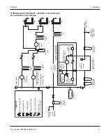
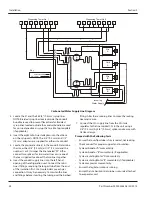
PLUMBING CIRCUIT DIAGRAMS — MODELS 42, 44 AND SC1000
Pressurized Water Circuit Diagram
To
Cof
fee
Machine
To
Ice
Machin
e
Legend
Phosphat
e
Feeder (optional)
Accumulator
Ta
nk
(optional)
To
Plain
Wa
ter
Va
lv
e
Filtered
Wa
ter
Pressure Gaug
e
Primary
Carbonator
Cooling
Coil
Carbonator
Tank
Cooling
Coil
Cooling
Coil
Circulator
Pump
To
wer
Tower
Tower
Optional Constant
Wa
ter
Pressure Booster Module
Booste
r
Tank
High
Pressure Switch
H
L
High
Pressure Gauge
Lo
w
Pressure Switch
Constant Pressure
Booster Pump
Pump
Pressure Regulator (55 psi [3.8 bar])
Low
Pressure Gauge
Fine
Filters
(optional)
Coarse Filter
(optional)
To
Optional
Wa
ter-Cooled
Condenser
Primary
Wa
ter Supply
Booster Module Replacement Line
— Electric Solenoid V
alv
e
— Manual Ball V
alv
e
— 3-way Ball V
alv
e
— Pressure Relief V
alv
e
— Check V
alve, Ball
Ty
pe
— Check V
alve,
—
Vent to
Atmospher
e
Secondary Carbonator
(Not Used On 42M)
Cooling
Coil


