4-7
Section 4
Maintenance
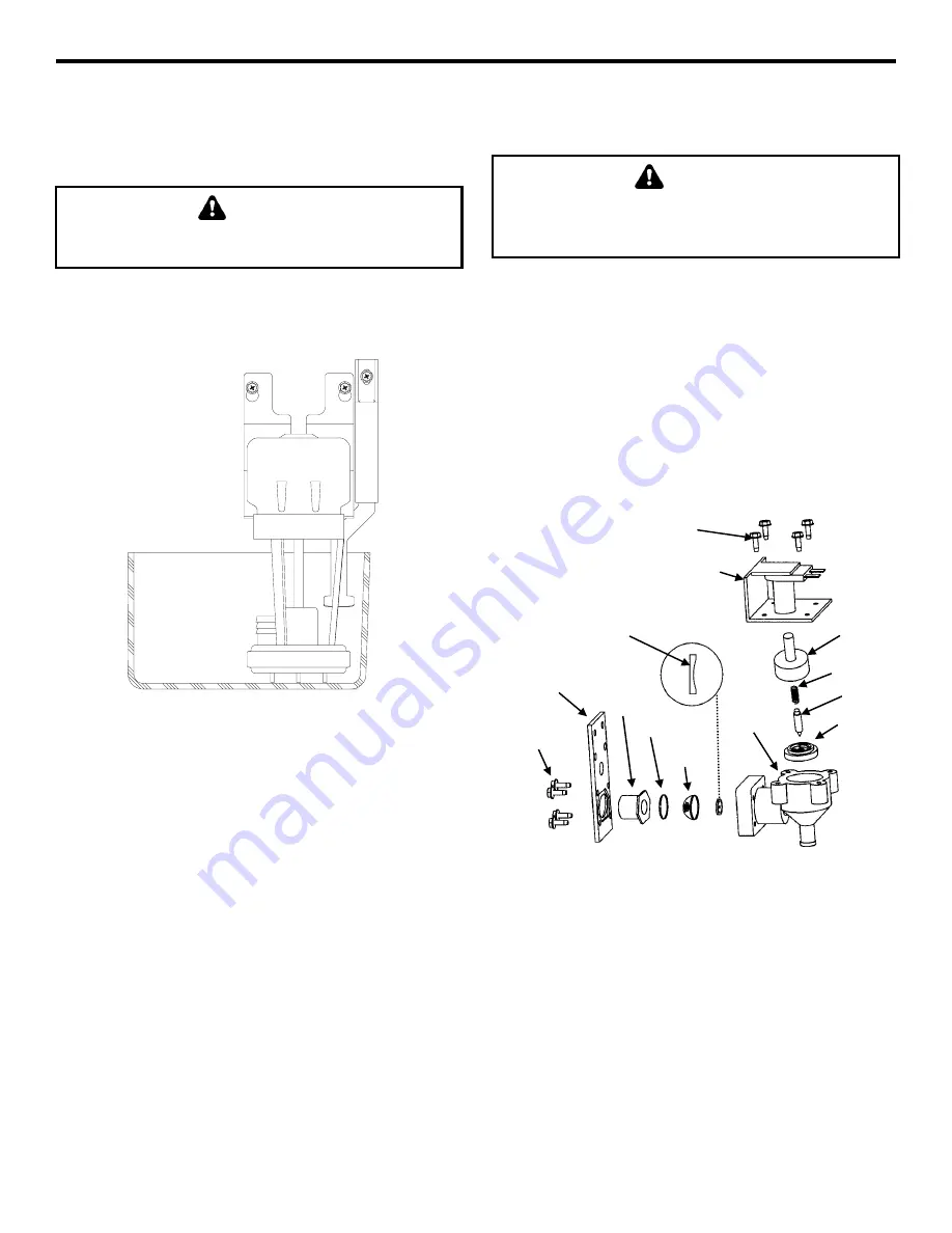
Water Level Probe
1.
Loosen the screw that holds the water level probe
in place. The probe can easily be cleaned at this
point without proceeding to step 2.
WARNING
Disconnect the electrical power to the ice machine
at the electrical disconnect before proceeding.
2.
If complete removal is required, disconnect the
wire lead from the control board inside the
electrical control box.
Water Level Probe Removal
Water Inlet Valve
The water inlet valve normally does not require
removal for cleaning. Follow the instructions below
to determine if removal is necessary.
1.
Set the ICE/OFF/CLEAN switch to OFF. Locate
the water inlet valve (in the water area of the ice
machine). It pours water into the water trough.
2.
When the ice machine is off, the water inlet valve
must completely stop water flow into the
machine. Watch for water flow. If water flows,
remove, disassemble and clean the valve.
3.
When the ice machine is on, the water inlet valve
must allow the proper water flow through it. Set
the toggle switch to ON. Watch for water flow
into the ice machine. If the water flow is slow or
only trickles into the ice machine remove
disassemble, and clean the valve.
Follow the procedure below to remove the water inlet
valve.
WARNING
Disconnect the electric power to the ice machine at
the electric service switch box and turn off the
water supply before proceeding.
1.
Remove the valve shield if necessary.
2.
Remove the filter access screws that hold the
valve in place.
NOTE: The water inlet valve can be disassembled
and cleaned without disconnecting the incoming
water supply line to the ice machine.
3.
Remove, clean, and install the filter screen.
4.
If necessary, remove the enclosure tube access
screws to clean interior components.
Exploded View of Water Inlet Valve
FILTER
ACCESS
SCREWS
MOUNTING
PLATE
FITTING
O-RING
FILTER
SCREEN
VALVE
BODY
RESTRICTOR
(FLAT SIDE MUST
FACE OUT)
RUBBER
SEAL
PIN
SPRING
ENCLOSURE
TUBE
ELECTRICAL
SOLENOID
ENCLOSURE
TUBE ACCESS
SCREWS
SV1699B
SV1623
Summary of Contents for P Series
Page 2: ...Part Number 80 1125 3 ...
Page 4: ......
Page 11: ...1 4 General Information Section 1 THIS PAGE INTENTIONALLY LEFT BLANK ...
Page 24: ...3 3 Section 3 Ice Machine Operation THIS PAGE INTENTIONALLY LEFT BLANK ...
Page 27: ...3 6 Ice Machine Operation Section 3 THIS PAGE INTENTIONALLY LEFT BLANK ...


