6-8
Section 6
Service
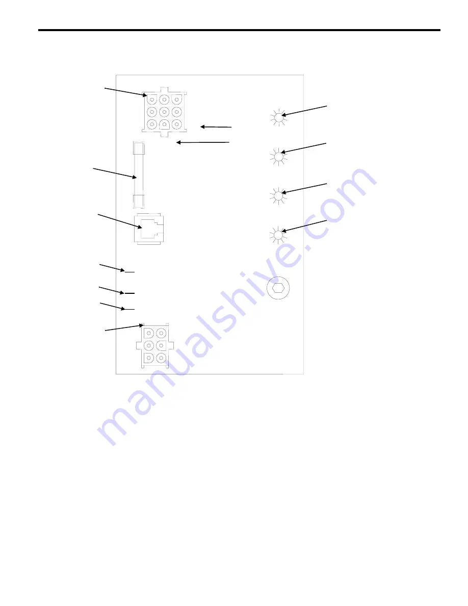
ELECTRONIC CONTROL BOARD
Control Board
General
P-Model control boards use a dual voltage
transformer. This means only one control board is
needed for both 115V and 208-230V use.
The control board along with inputs controls all
electrical components, including the ice machine
sequence of operation. Prior to diagnosing, you
must understand how the inputs affect the control
board operation.
Refer to specific component specifications
(inputs), wiring diagrams and ice machine
sequence of operation sections for details.
As an example, refer to “Ice Thickness Probe” in
the service section of this manual for information
relating to how the probe and control board
functions together.
This section will include items such as:
•
How a harvest cycle is initiated
•
How the harvest light functions with the probe
•
Freeze time lock-in feature
•
Maximum freeze time
•
Diagnosing ice thickness control circuitry
1G
N 115V
L
2
208-230V
L
1
PRIMARY
POWER SUPPLY
SV1588
1F
1C
57
55
58
60
61
56
20
AUTOMATIC CLEANING
SYSTEM (AuCS)
ACCESSORY PLUG
ICE THICKNESS
PROBE
(3/16” CONNECTION)
WATER LEVEL
PROBE
JUMPER USED ON
Q1300/Q1800 ONLY
68
65
67
63
62
DC LOW VOLTAGE
ELECTRICAL PLUG
(NUMBERS MARKED
ON WIRES)
MAIN FUSE (7A)
AC LINE VOLTAGE
ELECTRICAL PLUG
(NUMBERS MARKED ON
WIRES)
HARVEST LIGHT/
SAFETY LIMIT
CODE LIGHT
RED
BIN SWITCH LIGHT
GREEN
WATER LEVEL
PROBE LIGHT
GREEN
CLEAN LIGHT
YELLOW
Summary of Contents for P Series
Page 2: ...Part Number 80 1125 3 ...
Page 4: ......
Page 11: ...1 4 General Information Section 1 THIS PAGE INTENTIONALLY LEFT BLANK ...
Page 24: ...3 3 Section 3 Ice Machine Operation THIS PAGE INTENTIONALLY LEFT BLANK ...
Page 27: ...3 6 Ice Machine Operation Section 3 THIS PAGE INTENTIONALLY LEFT BLANK ...


