background image


1-3 

Section 1


General Information


Owner Warranty Registration Card 

GENERAL 

The packet containing this manual also includes 
warranty information. Warranty coverage begins the 
day your new ice machine is installed. 

Important


Complete and mail the OWNER WARRANTY 
REGISTRATION CARD as soon as possible to 
validate the installation date. 


If you do not return your OWNER WARRANTY 
REGISTRATION CARD, Manitowoc will use the 
date of sale to the Manitowoc Distributor as the first 
day of warranty coverage for your new ice machine. 

Warranty Coverage 

GENERAL 

The following Warranty outline is provided for your 
convenience. For a detailed explanation, read the 
warranty bond shipped with each product. 

Contact your local Manitowoc representative or 
Manitowoc Ice, Inc. if you need further warranty 
information. 

Important


This product is intended exclusively for 
commercial application. No warranty is extended 
for personal, family, or household purposes. 


PARTS 

1.


Manitowoc warrants the ice machine against 
defects in materials and workmanship, under 
normal use and service for three (3) years from 
the date of original installation. 

2.


The evaporator and compressor are covered by an 
additional two (2) year (five years total) warranty 
beginning on the date of the original installation. 

LABOR 

1.


Labor required to repair or replace defective 
components is covered for three (3) years from 
the date of original installation. 

2.


The evaporator is covered by an additional two (2) 
year (five years total) labor warranty beginning 
on the date of the original installation. 

EXCLUSIONS 

The following items are not included in the ice 
machine’s warranty coverage: 
1.


Normal maintenance, adjustments and cleaning as 
outlined in this manual. 

2.


Repairs due to unauthorized modifications to the 
ice machine or use of non-standard parts without 
prior written approval from Manitowoc Ice, Inc. 

3.


Damage caused by improper installation of the 
ice machine, electrical supply, water supply or 
drainage, or damage caused by floods, storms, or 
other acts of God. 

4.


Premium labor rates due to holidays, overtime, 
etc.; travel time; flat rate service call charges; 
mileage and miscellaneous tools and material 
charges not listed on the payment schedule. 
Additional labor charges resulting from the 
inaccessibility of equipment are also excluded. 

5.


Parts or assemblies subjected to misuse, abuse, 
neglect or accidents. 

6.


Damage or problems caused by installation, 
cleaning and/or maintenance procedures 
inconsistent with the technical instructions 
provided in this manual. 

7.


This product is intended exclusively for 
commercial application. No warranty is extended 
for personal, family, or household purposes. 

AUTHORIZED WARRANTY SERVICE 

To comply with the provisions of the warranty, a 
refrigeration service company, qualified and 
authorized by your Manitowoc distributor, or a 
Contracted Service Representative must perform the 
warranty repair. 

NOTE: If the dealer you purchased the ice machine 
from is not authorized to perform warranty service, 
contact your Manitowoc distributor or Manitowoc Ice, 
Inc. for the name of the nearest authorized service 
representative. 

SERVICE CALLS 

Normal maintenance, adjustments and cleaning as 
outlined in this manual are not covered by the 
warranty. If you have followed the procedures listed 
on page 5-1 of this manual, and the ice machine still 
does not perform properly, call your authorized 
service company. 

Summary of Contents for Q210 series

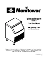
Page 1: ...u for selecting a Manitowoc Ice Machine the dependability leader in ice making equipment and related products With proper installation care and maintenance your new Manitowoc Ice Machine will provide you with many years of reliable and economical performance Part Number 000001130 01 07 ...

Page 2: ...tant Important boxes serve two functions They call the operator s attention to important information They also provide the service technician with information that may help perform a procedure more efficiently Disregarding this information may slow down the work NOTE Text set off as a Note provides you with simple but useful extra information Please read the following Safety Notices before proceed...

Page 3: ... Ice Machine Dimensions 2 1 Location of Ice Machine 2 3 Ice Machine Heat of Rejection 2 3 Leveling the Ice Machine 2 4 Electrical Service 2 5 Water Service Drains 2 6 Installation Checklist 2 8 Before Starting the Ice Machine 2 8 Section 3 Ice Machine Operation Component Identification 3 1 Ice Making Sequence of Operation 3 2 Energized Parts Chart 3 3 Operational Checks General 3 4 Siphon System 3...

Page 4: ...al 4 1 Interior Cleaning and Sanitizing 4 1 Cleaning and Sanitizing Procedure 4 1 Ice Machine Inspection 4 8 Exterior Cleaning 4 8 Cleaning the Condenser 4 9 Removal from Service Winterization 4 10 Section 5 Before Calling for Service Checklist 5 1 Safety Limit Feature 5 2 ...

Page 5: ...nt dependable and affordable method of inhibiting scale formation filtering sediment and removing chlorine taste and odor MANITOWOC CLEANER AND SANITIZER Manitowoc Ice Machine Cleaner and Sanitizer are available in convenient 16 oz 473 ml and 1 gal 3 78 l bottles These are the only cleaner and sanitizer approved for use with Manitowoc products Cleaner Part Number Sanitizer Part number 16oz 94 0456...

Page 6: ...istributor service representative or Manitowoc Ice Inc Q130 Q210 MODELS The model and serial number are listed on the OWNER WARRANTY REGISTRATION CARD They are also listed on the MODEL SERIAL NUMBER DECAL affixed to the ice machine Q270 MODELS Model Serial Number Location Ice Machine Model Number Serial Number MODEL SERIAL NUMBER PLATE MODEL SERIAL NUMBER PLATE PT1295 SV1687G MODEL SERIAL NUMBER P...

Page 7: ...ed in the ice machine s warranty coverage 1 Normal maintenance adjustments and cleaning as outlined in this manual 2 Repairs due to unauthorized modifications to the ice machine or use of non standard parts without prior written approval from Manitowoc Ice Inc 3 Damage caused by improper installation of the ice machine electrical supply water supply or drainage or damage caused by floods storms or...

Page 8: ...1 4 General Information Section 1 THIS PAGE INTENTIONALLY LEFT BLANK ...

Page 9: ...nitowoc Ice Inc for information regarding start up services Important Failure to follow these installation guidelines may affect warranty coverage Ice Machine Dimensions Q130 Q210 ICE MACHINES SV1688B CONDENSER WATER OUTLET CONDENSER WATER INLET ICE MAKING WATER INLET ICE MAKING WATER BIN DRAIN ELECTRICAL INLET 6 00 15 2CM 32 50 82 5CM 19 00 48 2CM 26 00 66CM 26 50 67 3CM 15 25 38 7CM 12 28 31 2CM...

Page 10: ... 71 5CM 13 48 34 2CM 12 36 31 3CM 12 36 31 3CM 8 80 22 3CM 6 48 16 4CM 32 50 115CM 20 69 52 5CM 30 0 76 2CM 1 25 3 1CM 2 12 5 4CM 6 0 15 2CM ELECTRICAL INLET 2 FPT WATER COOLED CONDENSER OUTLET 1 2 FPT WATER COOLED CONDENSER INLET 1 2 FPT BIN DRAIN 3 8 FPT ICE MAKING WATER INLET PT1294A ...

Page 11: ...ned Air Cooled Self Contained Water Cooled Top Sides 5 203 mm 5 127 mm Back 5 127 mm 5 127 mm NOTE The ice machine may be built into a cabinet There is no minimum clearance requirement for the top or left and right sides of the ice machine The listed values are recommended for efficient operation and servicing only CAUTION The ice machine must be protected if it will be subjected to temperatures b...

Page 12: ... position 4 Level the ice machine to assure that the siphon system functions correctly Use a level on top of the ice machine Turn each foot as necessary to level the ice machine from front to back and side to side NOTE An optional 2 caster assembly is available for use in place of the legs on the Q130 Q210 and Q270 Installation instructions are supplied with the casters Checking Ice Machine Level ...

Page 13: ...ss of power presumably to ground Manitowoc Ice Inc does not recommend the use of a GFCI GFI circuit protection with our equipment If code requires the use of a GFCI GFI then you must follow the local code The circuit must be dedicated sized properly and there must be a panel GFCI GFI breaker We do not recommend GFCI GFI outlets as they are known for more intermittent nuisance trips than panel brea...

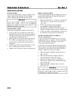
Page 14: ...achine and storage bin Drain lines must have a 1 5 inch 3 8 cm drop per 5 feet of run 2 5 cm per meter and must not create traps The floor drain must be large enough to accommodate drainage from all drains Run separate bin and water cooled condenser drain lines Insulate them to prevent condensation Vent the bin drain to the atmosphere Do not vent the condenser drain on water cooled models COOLING ...

Page 15: ...minimum inside diameter Condenser Water Inlet 33 F 0 6 C Min 90 F 32 2 C Max 20 psi 137 9 kPA Min 150 psi 1034 2 kPA Max 1 2 Female Pipe Thread 1 2 12 7 mm minimum inside diameter Condenser Water Drain 1 2 Female Pipe Thread 1 2 12 7 mm minimum inside diameter Bin Drain 1 2 Female Pipe Thread 1 2 12 7 mm minimum inside diameter Typical Water Supply Drain Installation BIN DRAIN CONDENSER WATER DRAI...

Page 16: ...the owner operator been instructed regarding maintenance and the use of Manitowoc Cleaner and Sanitizer Has the owner operator completed the warranty registration card Has the ice machine and bin been sanitized Has this manual been given to the owner operator Is the float valve in the OPEN position Before Starting the Ice Machine All Manitowoc ice machines are factory operated and adjusted before ...

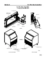
Page 17: ...FF WASH TOGGLE SWITCH CONDENSER AIR FILTER EVAPORATOR Q210 Q270 SHOWN ICE DAMPER WATER TROUGH DISTRIBUTION TUBE Q210 Q270 SHOWN ICE THICKNESS PROBE FLOAT VALVE SIPHON CAP BIN SWITCH SV1695G SV1695A SV1686G Q130 Q210 ICE MACHINES Q270 ICE MACHINES PT1288 COMPRESSOR COMPARTMENT ACCESS SCREWS ON OFF WASH TOGGLE SWITCH CONDENSER AIR FILTER ...

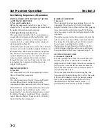
Page 18: ...e ice contacts the ice thickness probe After approximately 7 seconds of continual water contact the Harvest Sequence is initiated The ice machine cannot initiate a Harvest Sequence until a 6 minute freeze time has been surpassed HARVEST SEQUENCE 5 Harvest The water pump de energizes stopping flow over the evaporator The rising level of water in the sump trough diverts water out of the overflow tub...

Page 19: ... 1 Pressure Equalization OFF ON OFF OFF OFF 15 Seconds 2 Refrigeration System Start up OFF ON ON ON ON 5 Seconds FREEZE SEQUENCE 3 Pre Chill OFF OFF ON ON ON 30 Seconds 4 Freeze ON OFF ON ON ON Until 7 sec water contact with ice thickness probe HARVEST SEQUENCE 5 Harvest OFF ON ON ON ON Bin switch activation AUTOMATIC SHUT OFF 6 Auto Shut Off OFF OFF OFF OFF OFF Until bin switch re closes Condense...

Page 20: ...he warranty SIPHON SYSTEM To reduce mineral build up and cleaning frequency the water in the sump trough must be purged during each harvest cycle When the water pump de energizes the level in the water trough rises above the standpipe starting a siphon action The siphon action stops when the water level in the sump trough drops When the siphon action stops the float valve refills the water trough ...

Page 21: ...s necessary then tighten the screws 5 Move the main ON OFF WASH toggle switch to the OFF position The water level in the trough will rise above the standpipe and run down the drain 6 Replace the siphon cap on the standpipe and verify water level and siphon action by repeating steps 3 through 5 ICE BRIDGE THICKNESS CHECK The ice thickness probe is factory set to maintain the ice bridge thickness at...

Page 22: ...3 6 Ice Machine Operation Section 3 THIS PAGE INTENTIONALLY LEFT BLANK ...

Page 23: ... solutions in a manner inconsistent with their labeling WARNING Wear rubber gloves and safety goggles and or face shield when handling Ice Machine Cleaner or Sanitizer Ice machine cleaner is used to remove lime scale and mineral deposits Ice machine sanitizer disinfects and removes algae and slime Step 1 Set the toggle switch to the OFF position after ice falls from the evaporator at the end of a ...

Page 24: ... the ice thickness probe wire to the bulkhead grommet exit point in the back wall Pop the bulkhead grommet out of the back wall by inserting fingernails or a flat object between the back wall and the grommet and prying forward Pull the bulkhead grommet and wire forward until the connector is accessible then disconnect the wire lead from the connector Ice Thickness Probe Cleaning Mix a solution of ...

Page 25: ... the inner tube ends until the tabs line up with the keyways Pull the inner tube ends outward Water Distribution Tube Disassembly Q130 Models Water Distribution Tube Removal Loosen the two thumbscrews which secure the distribution tube Lift the distribution tube up off the thumbscrews Disassembly Twist the barbed end until the tab lines up with the keyway Pull the inner tube end outward SV1211 INN...

Page 26: ...ap and filter screen for cleaning F Remove the Water Trough Apply downward pressure on the siphon tube and remove from the bottom of the water trough Remove the upper thumbscrew While supporting the water trough remove the two thumbscrews from beneath the water trough Remove the water trough from the bin area SPLASH SHIELD FLOAT SHUT OFF VALVE COMPRESSION FITTING FLOAT VALVE BRACKET SV1695 2 CAP A...

Page 27: ...t the left hand mounting bracket push the damper until the right hand mounting pin engages Q210 Q270 Grasp ice damper and apply pressure toward the left hand mounting bracket Apply pressure to the right hand mounting bracket with thumb Pull ice damper forward when the right hand ice damper pin disengages Installation Place ice damper pin in left hand mounting bracket and apply pressure toward the ...

Page 28: ... l 16 oz 500 ml cleaner Step 8 Use of the cleaner water solution to clean all components The cleaner solution will foam when it contacts lime scale and mineral deposits once the foaming stops use a soft bristle brush sponge or cloth not a wire brush to carefully clean the parts Soak the parts for 5 minutes 15 20 minutes for heavily scaled parts Rinse all components with clean water Step 9 While co...

Page 29: ...o the ice machine WARNING Disconnect electric power to the ice machine at the electric switch box before proceeding Step 17 Repeat step 6 to remove parts for hand sanitizing Step 18 Mix a solution of sanitizer and warm water Solution Type Water Mixed With Sanitizer 6 gal 23 l 4 oz 120 ml sanitizer Step 19 Use 1 2 of the sanitizer water solution to sanitize all removed components Use a cloth or spo...

Page 30: ...chine There must be adequate airflow through and around the ice machine to maximize ice production and ensure long component life EXTERIOR CLEANING Clean the area around the ice machine as often as necessary to maintain cleanliness and efficient operation Sponge any dust and dirt off the outside of the ice machine with mild soap and water Wipe dry with a clean soft cloth A commercial grade stainle...

Page 31: ...ough the condenser to check for dirt between the fins If dirt remains Blow compressed air through the condenser fins from the inside Be careful not to bend the fan blades 4 Use a commercial condenser coil cleaner Follow the directions and cautions supplied with the cleaner 5 Straighten any bent condenser fins with a fin comb 6 Carefully wipe off the fan blades and motor with a soft cloth Do not be...

Page 32: ...ve the water from the water trough 4 Disconnect and drain the incoming ice making water line at the rear of the ice machine 5 Blow compressed air in both the incoming water and the drain openings in the rear of the ice machine until no more water comes out of the inlet water lines or the drain 6 Make sure water is not trapped in any of the water lines drain lines distribution tubes etc WATER COOLE...

Page 33: ...4 11 Section 4 Maintenance THIS PAGE INTENTIONALLY LEFT BLANK ...

Page 34: ...4 12 Maintenance Section 4 THIS PAGE INTENTIONALLY LEFT BLANK ...

Page 35: ...ine is not level Level the ice machine See page 2 4 Low air temperature around ice machine air cooled models Air temperature must be at least 35 F 1 7 C Water regulating valve leaks in harvest mode water cooled models Replace water regulating valve Ice machine does not cycle into harvest mode The six minute freeze time lock in has not expired yet Wait for freeze lock in to expire Ice thickness pro...

Page 36: ...alve and clean it See page 4 4 The condenser is dirty Clean the condenser See page 4 9 High air temperature around ice machine air cooled models Air temperature must not exceed 110 F 43 3 C Inadequate clearance around the ice machine Provide adequate clearance See page 2 3 Objects stacked around ice machine blocking airflow to condenser air cooled models Remove items blocking airflow Safety Limit ...

Page 37: ...flashing continuously Determining Which Safety Limit Stopped The Ice Machine When a safety limit condition causes the ice machine to stop the harvest light on the control board continually flashes on and off Use the following procedures to determine which safety limit has stopped the ice machine 1 Move the toggle switch to OFF 2 Move the toggle switch back to ON 3 Watch the harvest light It will f...

Page 38: ...on Manitowoc components Improper refrigerant charge Defective hot gas valve Defective compressor TXV starving or flooding check insulation and bulb mounting Non condensables in refrigeration system Plugged or restricted high side refrigerant lines or component Safety Limit 2 Harvest time exceeds 3 5 minutes for 3 consecutive harvest cycles Possible Cause Check Correct Improper installation See Ins...

Page 39: ......

Page 40: ...MANITOWOC ICE INC Web Site www manitowocice com 2005 Manitowoc Ice Inc We reserve the right to make product improvements at any time Specifications and design are subject to change without notice ...

Reviews: