135
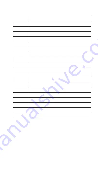
Wiring Diagram Legend RNF1020C Head Section
1
Gear Motor
6
Water inlet valve
10
Low water level switch
11
Bin thermostat
17
Water level switch
18
Chute safety switch
21
Relay
24
On/Off switch
30
Rotation sensor
35
Compressor time delay by-pass (Service Staff only)
38
Solenoid Valve
Wire Color Designation
A
Orange
B
White
BL
Blue
G
Grey
M
Brown
N
Black
R
Red
V
Violet
Summary of Contents for RFF
Page 2: ......
Page 34: ...THIS PAGE INTENTIONALLY LEFT BLANK 34 Part Number 000015433_03 5 20 ...
Page 146: ...THIS PAGE INTENTIONALLY LEFT BLANK 146 Part Number 000015433_03 5 20 ...
Page 160: ...THIS PAGE INTENTIONALLY LEFT BLANK 160 Part Number 000015433_03 5 20 ...
Page 161: ......
Page 162: ......
Page 163: ......


