background image

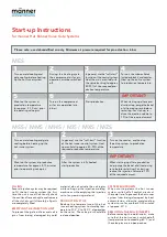
mss / mms / mhs / mis / mXs / mZs

start-up instructions

for männer Hot Runner Valve Gate Systems

Please note: use dehumidified air only. minimum air pressure required for pin actuation: 6 bar. 

fillinG

Several injection cycles may be required 

to fill the hot runner system the first 

time the unit is used. Continually check 

the cavities after each cycle and remove 

all short shots until ultimately all parts 

are completely filled. 

emPTyinG The inJecTion uniT

To prevent the gate orifices and valve 

pins  from  being  damaged  by  cold  

material, do not actuate the valve pins 

while setting up the injection molding 

machine or while emptying the injection 

unit of any remaining material. 

ProDucTion sToP

Reduce  the  temperature  of  the  hot  

runner heating system to standby tem-

perature (100° C to 150° C, depending 

on the resin). The valve pins should be 

in closed position.  

mes

sysTem shuTDoWn

When  shutting  down  the  hot  runner 

system, switch off all control circuits at 

the same time. To prevent the hot runner 

system from being damaged by heat 

accumulation, allow the mold cooling 

system to run for another 20-30 minutes 

at approx. 30° C.

remoVinG The molD inserTs

Before removing the mold inserts, make 

sure that the hot runner is switched off 

(temperature not exceeding 60° C) and 

the valve pins are in open position.

Turn on the submanifolds 

(cylinder blocks) and nozzles. 

Heat up the entire system  

to production temperature. 

In general, use the “soft-start“ 

function of the control system. 

Heat the main manifold with 

the sprue bushing to approx. 

80-90% of the required pro-

duction temperature.

During the heating cycle, 

the compressed air for pin 

operation must be switched 

off.  

Turn on mold cooling and 

gate cooling before heating 

up the hot runner system. 

When starting up after a pro-

duction stop, purge the barrel 

of all remaining resin before 

restarting. For start-up, re-

duce the injection volume to 

70% of the required amount.

Start production.

Turn on the compressed 

air for pin operation (min. 

6 bar).

Maintain the system at 

production temperature 

for approx. 5 -10 min. prior 

to operating valve pins. 

1

2

3

4

5

6

7

imPorTanT!

Turn on the nozzles, and heat up 

the entire system to production 

temperature.

In general, use the “soft-start“ function 

of the hot runner control system. Heat 

up manifold to approx. 80-90% of the 

required production temperature. 

Turn on mold cooling and gate  

cooling before heating up the  

hot runner system.  

When starting up after a production 

stop, purge the barrel of all remaining 

resin before restarting. For start-up, 

reduce the injection volume to 70%  

of the required amount.

After the system is fully heated,  

start production.

Maintain the system at production 

temperature for approx. 5-10 minutes 

prior to operating valve pins.

1

4

imPorTanT!

2

3

5

Summary of Contents for MES

Page 1: ...Technical information hot runner systems ...

Page 2: ...ins are in open position Turn on the submanifolds cylinder blocks and nozzles Heat up the entire system to production temperature In general use the soft start function of the control system Heat the main manifold with the sprue bushing to approx 80 90 of the required pro duction temperature During the heating cycle the compressed air for pin operation must be switched off Turn on mold cooling and...

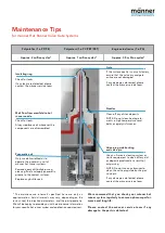
Page 3: ...ate orifice are not damaged If any damage is detected please contact the männer service team Valve pin guide bushing and valve pin Use an ultrasonic cleaning system or similar equipment to clean off any dirt or deposits produced as a result of outgassing NOTE Do not use any abrasives to clean the valve pin guide bushing or valve pin If any damage is detected please contact the männer service team ...

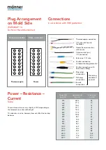
Page 4: ...rule for blocks 3 Heater band connection with ferrule 4 Crimp contact pin 1 5 connection 5 Extension 1 5 wire 6 Parallel connection 2 tubular heating elements 7 Parallel connection with heat shrink tubing 8 Ring plug connection 9 Flat plug connection 10 Ferrule connection Grounding conductors on mold 1 2 3 4 5 6 7 8 9 10 11 12 13 14 15 16 9 10 11 12 13 14 15 16 1 2 3 4 5 6 7 8 N L Thermocouple Pow...

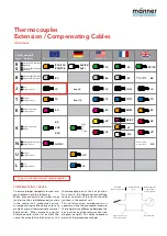
Page 5: ...his helps to prevent parasitic thermocouple voltages Thermocouples Extension Compensating Cables Overview Type J is used for männer thermocouples Thermocouple T E K N U L Type Material IEC 60584 DIN IEC 584 DIN 43710 BC 4937 See LX See UX Color coding not specified Color coding not specified RX SX BX JX TX EX KX VX NX R S B J Iron Copper nickel Copper Copper nickel Nickel chromium Copper nickel UX...

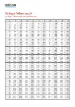
Page 6: ...032 6579 7129 7679 8231 8783 9337 9891 10446 11001 11556 12111 12667 13222 13777 14332 14887 15441 15995 16549 17102 17655 18207 18759 19311 19863 20414 20966 21517 22069 22620 23172 23725 24278 24832 25386 253 762 1277 1797 2322 2850 3382 3918 4456 4997 5541 6087 6634 7184 7734 8286 8839 9392 9947 10501 11056 11612 12167 12722 13278 13833 14388 14942 15496 16050 16604 17157 17710 18262 18814 1936...

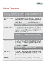
Page 7: ...o cess output and increases or decreases the control output until the deviation is zero The control output is maintained until a new error arises The characte ristic parameter is the reset time Tv which can be set to a value from 0 0 to 999 0 seconds Cycle time T1 The cycle time is the time required to complete the heating and pause actions for a specific power setting The cycle time can be set to...

Page 8: ...GmbH Unter Gereuth 9 11 79353 Bahlingen a K Germany Phone 49 0 7663 609 0 Fax 49 0 7663 609 299 info maenner group com www maenner group com 02 12 Technical specifications subject to change Actual colors may differ ...

Reviews: