9. Diagnostics and Fault Clearance
• DOK-CONTRL-DDC+MDD+DLC-ANW1-EN-E1,44 • 01.97
101
9.3.
Diagnostics Possibilities with a CTA
Programming and Display Unit
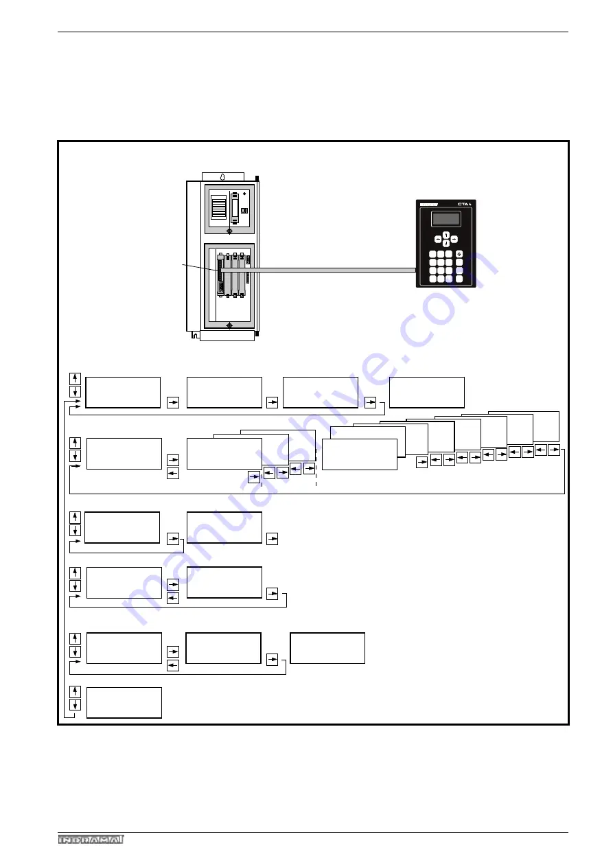
With the use of a CTA programming and display unit it is possible to access
the high-performance display system of the DLC.
Fig 9.2: Display system of the DLC
97-99
E: 1010 counter
Position display
E 1250 PSA
in setup mode
Program input
in setup mode
DLC1.1
DA 01.1-00.0
State input/output
Display after switching on:
in setup mode
Speed
Actual speed rpm
inputs 01-07
08-22
23-37
Outputs 01-16
17-32
33-48
49-64 65-80
81-96
system ready
If cursor in line 1: + = block 1
- = block number -1
1..1...
................
..........
..........
..... .....
..... .....
..... .....
System outputs
1.1..
Option E/A-Erw. m.
DEA5 / DEA6
comm: 0000 rpm
act: +0000 rpm
Relative measurement
Pos.: -000003.12
SF : +000000.00
REST: -000000.00
System inputs
.11.1...
1 +123456.78 999
1
16
1
16
E: Progr.Status
Task1: 0000 NOP
Drive diagnosis
e.g.
A: 1010 counter
in automatic mode
Manual A1
Drive Diagnosis
100
Ready to operate
Controller type
Software version
A: Progr.Status
Task1: 0000 NOP
in automatic mode
in setup mode
FPeinrbe
CTA 4
Drive controller
e.g., DDC
SYSTEMKONFIGURATION
DLC
IKS 745
max. 30 m with unilluminated CTA
(max. 10 m with illuminated CTA)
A: NO START
in
automatic mode
CR
7
4
5
6
1
2
3
+
8
9
0
-
3
CL


