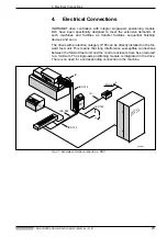
4. Electrical Connections
• DOK-CONTRL-DDC+MDD+DLC-ANW1-EN-E1,44 • 01.97
24
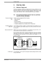
One feature of both the single-axis positioning module and the drive is their
considerable insusceptibility to systems and circuitry interference. Some
guidelines must, nonetheless, be observed during installation to avoid, to
the greatest possible extent, the affects of interference.
Avoid coupling in
interference
• Signal lines must basically be grounded with shields.
• With analog signals, the shield must generally be connected one-sided,
over the greatest possible surface area on the unit side of the chassis/
housing. With digital signals, it is advisable to lay the shield on both ends
of the cable over the greatest surface possible on the chassis/housing.
• Signal and control leads must be routed at least 10 cm away from power
cables. Routing in separate cable ducts is the best solution.
• Signal and control leads should only cross power cables at angle of 90
°
.
• Such inductive loads as contactors, relays and magnetic valves should
only be operated with suitable overvoltage limitors.
• Ground drives as per INDRAMAT guidelines.
Supplementary
documentation
See „Electromagnetic Compatibility (EMC) in AC Drives“, doc. no. 209-
0049-4305-01.


