4. Electrical Connections
• DOK-CONTRL-DDC+MDD+DLC-ANW1-EN-E1,44 • 01.97
26
4.2.
Controlling the Mains Contactor
Application
• If a synchronous motor, for example an MDD, is mounted to the DDC.
Features
DC bus dynamic braking always bring synchronous motors to a standstill
regardless of whether the electronics of the drive are still functional or not.
The DC bus dynamic brake is only applied when there is a problem in the
drive.
In the case of an emergency stop (E-stop) or if the machine is shut off, then
the drives are braked in a regulated manner by the electronics of the
drive at maximum torque.
How it works
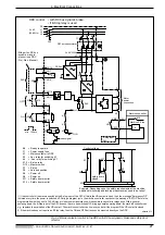
Once the E-stop relay closes, then the auxiliary relays K3 and K4 switch the
mains contactor on. If there is an error in K3 or K4, then it is not possible to
switch it on.
When the E-stop relay opens, then K3 and K4 safely switch the mains con-
tact K1 off. At the same time, the machine control switches the drive enable
signal (RF input with analog interface, E-stop input of the DEA 4 if the sin-
gle-axis positioning module DLC is used). This brings about, drive-internally,
a command value to zero of the drive. The drive is brought to a controlled
stop.
A drive error signal from the Bb contact of the DDS, an error message from
the NC control (servo error) or if the limit switch is overshot, then the mains
contactor is switched off and the DC bus dynamic brake applied.
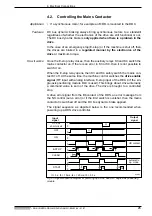
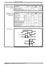
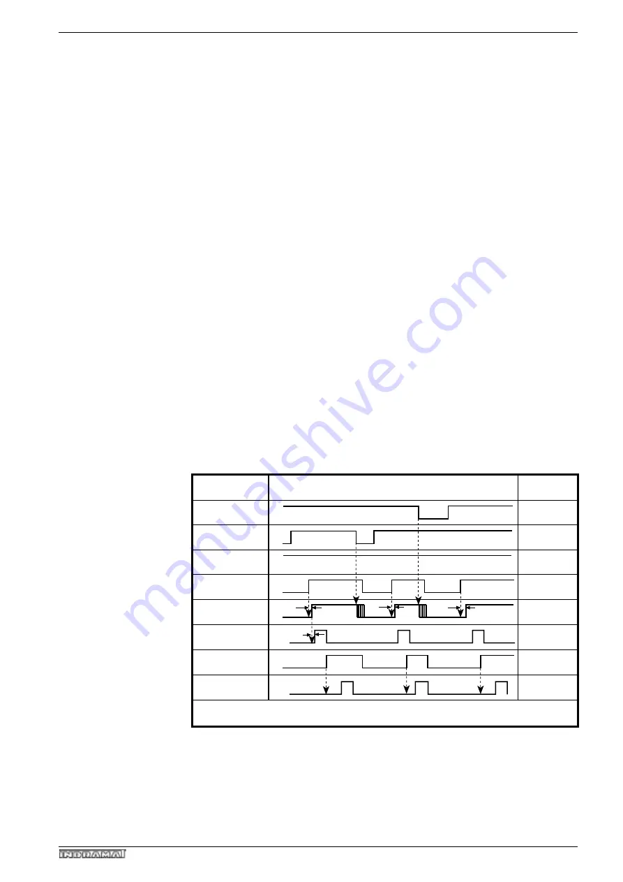
The signal sequence as depicted below is the one recommended when
powering up a DDS drive controller.
Fig 4.3: Signal sequence diagram for powering up a DDC with DLC single-axis positioning
module
Input
signal
DC bus
short circuit
OFF
ON
UD contact
CLEAR
Output
signal
1
0
1
0
1
0
1
0
1
0
E-STOP
1
0
1
0
1
0
automatic
op. mode
t1
t3
t3
t3
t4
t4
t4
t4
t4
t3
t5
t5
START
t1 > 3 s; t3 > 10 ms; t4 >= 20 ms; t5 > 0.3 s
t4
t5
SVDDC
t1


