4. Electrical Connections
• DOK-CONTRL-DDC+MDD+DLC-ANW1-EN-E1,44 • 01.97
34
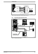
4.6.
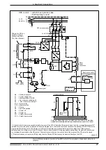
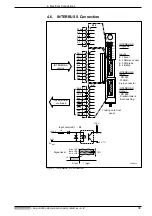
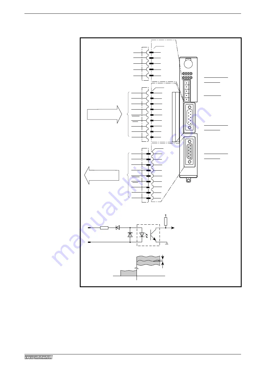
INTERBUS S Connection
Fig 4.11: INTERBUS S Connection
APDBS22
Looking onto front
panel
INTERBUS-S
Diagnosis
Inputs
E 1 Event
E 2 Reference cam
E 3 Lift brake
E 4 E-Stop
INTERBUS-S
Input
- RS 485
-D-SUB -
9-pin connector
INTERBUS-S
Output
- RS 485
-D-subminiature
9-pin bushing
0 Vext
3K
X39/2-5
0 V
TTL
X39/1
Signal level
+15 V
0 (low)
1 (high)
+3 V
10%
max +32 V
typic. +24 V
min. +18 V
Input circuits E1 … E4
X39
DO 2
DI 2
GND 2
free
+5 V 2
/DO 2
/DI 2
free
RBST
X41
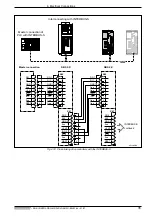
INTERBUS-S
continued
1
2
3
4
5
6
7
8
9
1
2
3
4
5
DBS 2.2
X41
X40
H1
H2
A B C D
1
2
3
4
5
6
7
8
9
DO 1
DI 1
GND 1
free
free
/DO 1
/DI 1
free
free
X40
INTERBUS-S
coming
1
2
3
4
5
6
7
8
9
1
2
3
4
5
6
7
8
9
1
2
3
4
5
0 Vext
E 1
E 2
E 3
E 4
X 39
OV
L
E1
E2
E3
E4

