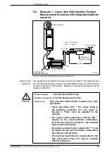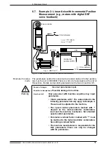
6. Parameter Input
• DOK-CONTRL-DDC+MDD+DLC-ANW1-EN-E1,44 • 01.97
52
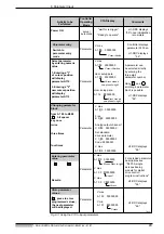
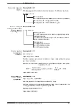
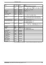
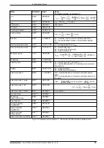
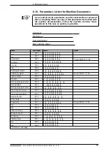
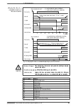
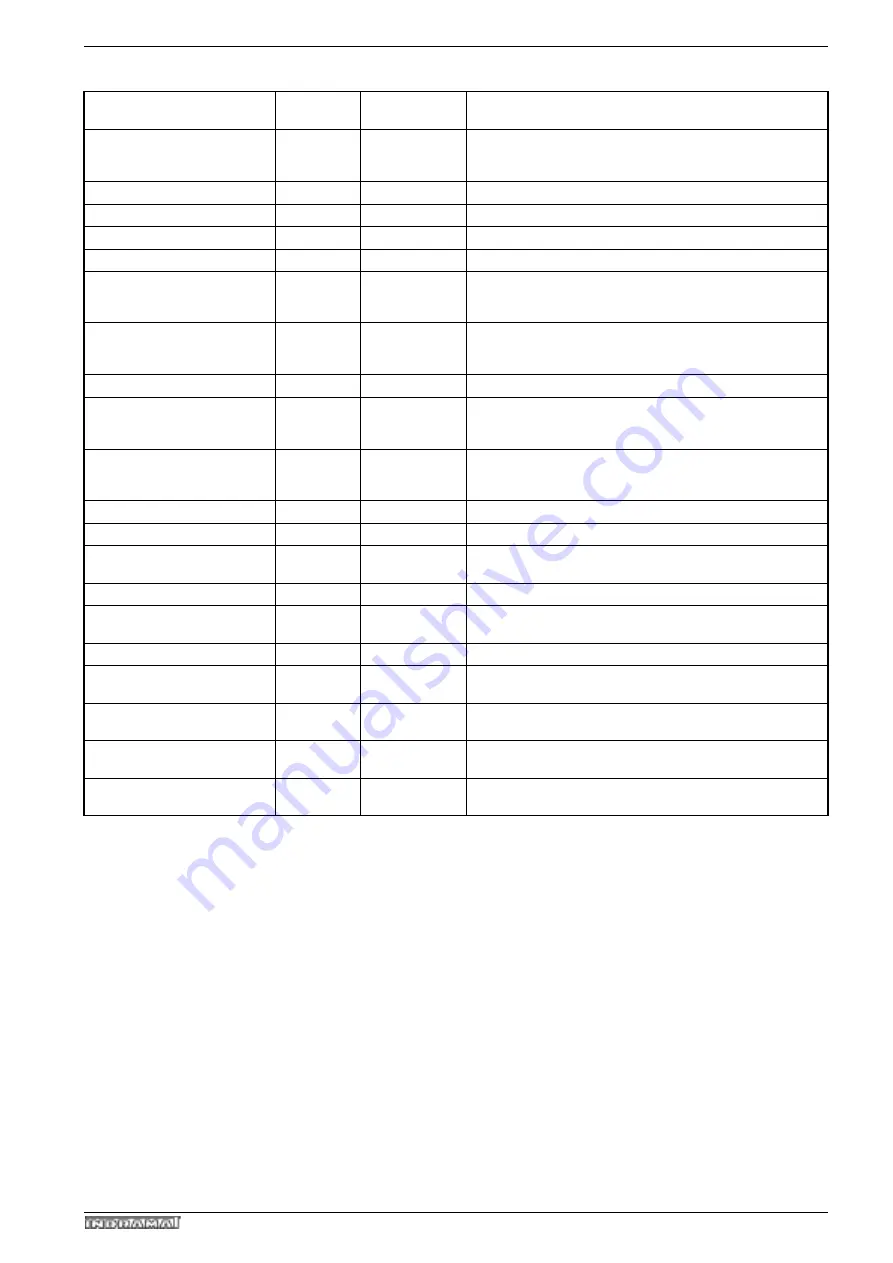
Fig 6.9: Parameter list for example 2 - linear axis with incremental position measurement
Name
Parameter
Input
Notes
(for further details see section 6.5)
v
max
A100
*
000300.00
v
min
A101 *
000030.00
e.g., 10% of
v
max
= 30 mm/s
Acceleration
A102 *
00001000
1000 mm/s
2
KV factor
A103 *
0000 01.00
Switching threshold
A106 *
00 0000.10
Feed constant
A108 *
0006.2500
Direction
A109 *
0 0 000000
00 = clockwise rotation of motor effects positive feed
01 = counterclockwise rotation of motor effects positive
feed
Homing setup parameter
A110 *
0 0 0 1 10 0 0
10 = Homing speed 10% of
v
max
Homing setup parameter
A112 *
01 02 00 03
01 = start homing input
02 = Homing point switch input
03 = Output in reference
Maximum speed
A121 *
2880 0000
Monitoring
A122
0 0 00 0 010
Interface
B003
0960 0 1 8 1
Display
B007
00 02 0 0 00
02 = standard setting
03 = additional decimal places
Overload factor
C002 ***
00000200
Monitoring
Speed control loop
C005
00000001
Error reaction
C008
00000000
Current regulator:
Amplification
C009 **
000012.00
Speed controller:
Amplification
C010 **
00001300
Speed controller:
Follow-up time
C011 **
0000020.0
Speed controller:
Smoothing
C012 **
00002000
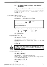
v
max
n
max
60
------------
h
•
=
Z
1
Z
2
-------
2880min
-1
60
---------------------------
=
•
10mm
35
56
------
•
•
300
mm
s
----------
=
VK
h
=
Z
1
Z
2
-------
•
10mm
=
35
56
------
•
6.25mm
=
n
max
v
max
60
•
h
-------------------------
=
Z
2
Z
1
-------
300mm
60s
•
s • min • 10mm
----------------------------------------
=
•
56
35
------
•
2880min
-1
=

