7. Commissioning
• DOK-CONTRL-DDC+MDD+DLC-ANW1-EN-E1,44 • 01.97
68
Check holding brake
load
• Call up parameter C 001
• Input 0000 0000.
• Switch on setup mode.
• The release of the holding brake must be audible.
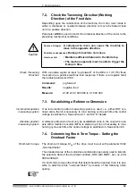
• Measure the voltage at analog output channel 2 (X3-3/4) with motor at
standstill.
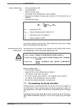
• Calculate load torque.
Load torque should not exceed 70% of the rated torque of the motor holding
brake as is specified in the data sheet.
Manual release of the
holding brake
If the feed axis is, for example, to be manually moved during a start-up, then
the holding brake can be released by applying 24V DC.
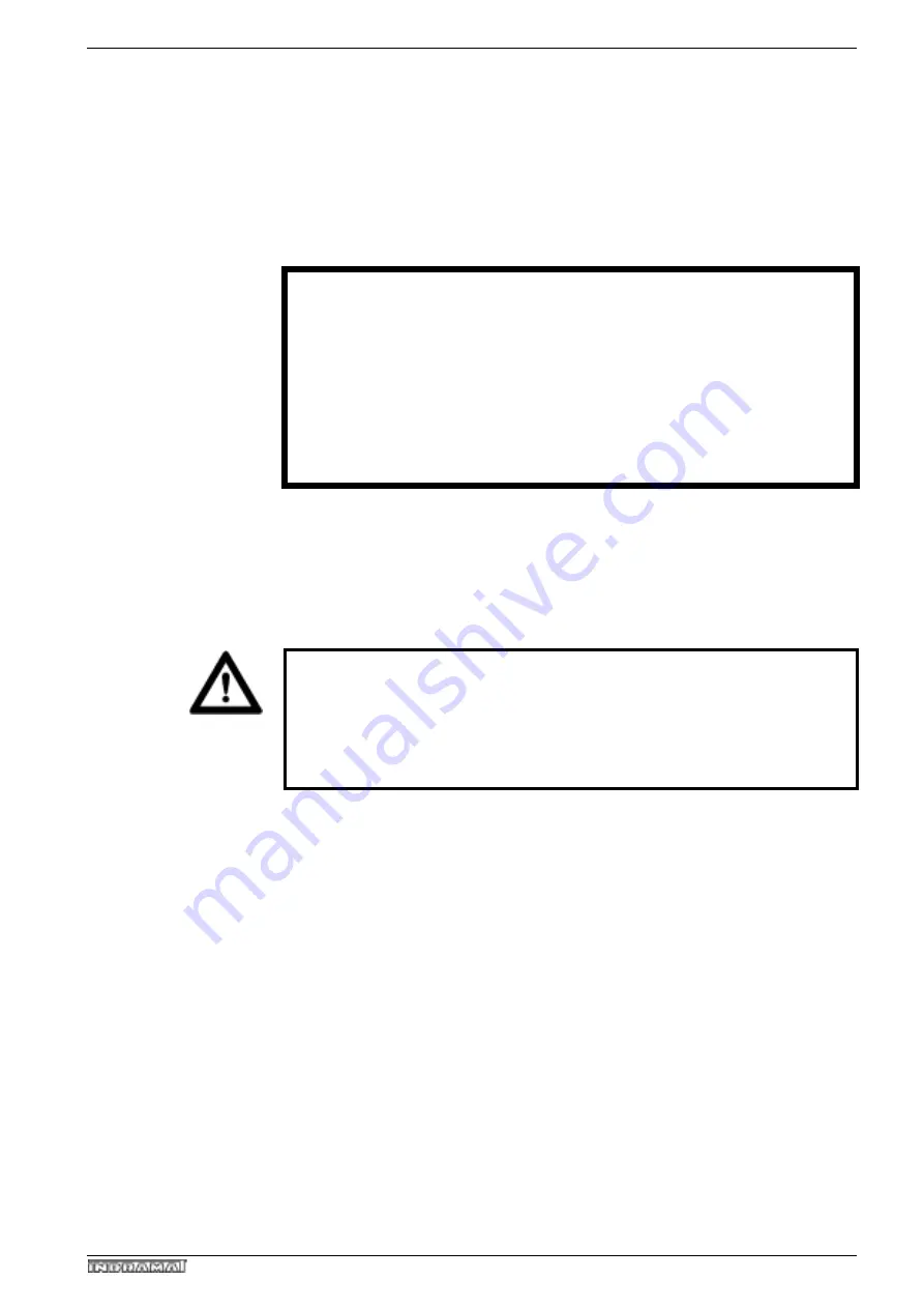
Warning
Release holding brake:
• Pull out motor connector
• Apply 24V DC to the holding brake connections
• +24V at pin F of the motor connector
• 0 V at pin G of the motor connector - use separate motor connector.
• The release of the holding brake must be audible.
• Reclamp the holding brake after moving the axis.
7.7.
Parametrizing the Speed Controller
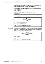
Standard speed controller parameters are stored in the motor feedback of
the MDD motor. These standard speed controller parameters suffice for
most applications. The speed controller does not generally need to be adap-
ted.
Standard speed controller parameters can be set with the use of a PC (emu-
lation software DDS2PC required) or via the CTA programming and display
unit.
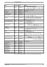
M
L
U
AK2
10V
-------------
I
typ
K
m
•
•
=
M
L
= load torque in Nm
U
AK2
= voltage at analog output channel 2 in V
I
typ
= rated current in A of equipment
K
m
= torque constant in Nm/A
Source of danger:
Danger of unintentional machine motions.
Possible consequences:
Injury and machine damage from slumping
feed axis.
How to avoid:
Secure suspended axes against unintentional
motion.

