8. Functions of the DLC Single-Axis Positioning Module
• DOK-CONTRL-DDC+MDD+DLC-ANW1-EN-E1,44 • 01.97
79
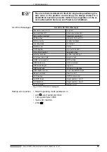
Setting the absolute
reference dimension
• Bring the feed axis to a measured position by jogging it there in setup
mode (match parameter A114 “Travel range maximum”, if necessary).
• Switch operating mode parameter on
• Check parameter A 109
• Call up parameter C 007 absolute encoder homing position.
• Input C 007
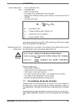
Example: In Figure 6.6 of section 6.6 the measured position (+600 mm) is
located in the center of the working range.
Parameter A 109 reads 0 1 000 000
Feed constant = 6.25 mm
Input value : 4000.0000
• hit
!
• switch operating mode off
• hit
until the position appears in the CTA display. The measured position
is displayed, e.g., + 000600.00.
Absolute encoder-
activate monitor
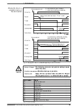
The current actual position is stored in the drive controller once control
voltage is off. Stored position and actual position are compared once it is
switched back on.
The permissible deviation is programmed in parameter C 006.
A 109 = 0 0 000 000
A 109 = 0 1 000 000
C007
position measured
feedconstant
-------------------------------------------------
=
C007
4096
position measured
feedconstant
-------------------------------------------------
+
=
C007
4096
600 mm
6.25 mm
-----------------------
4000
=
–
=
The permissible working range of the feed axis can still be overs-
hot. Enter working range limit in parameters A 113 and A 114.


