10
REMOTE INPUTS
The FRONT PANEL/REMOTE switch enables remote functions. Switching to FRONT PANEL disables the remote
functions, allowing the front panel controls to operate the pump.
When the FRONT PANEL/REMOTE switch is in the REMOTE position, starting and stopping the pump is controlled by
an external contact closure between pins 6 and 7 (Jumper B), and the pump speed is determined by an externally
supplied 2–10 V or 4–20 mA source. Connection must be made between pins 6 and 7 and a control voltage greater than
2 V or a control current greater than 4 mA must be applied for the pump to run.
If setting the speed from the front panel is desired with remote Start/Stop contact operation, the FRONT PANEL/
REMOTE must again be in the REMOTE position. In addition, Jumper A should be in place. Jumper A connects pin 5
of the “D” shell connector (REMOTE/LOCAL SPEED) to pin 6 (RETURN). Start/Stop will then be controlled from the
rear panel (Jumper B), and the pump speed will be controlled from the front panel. The accessory Footswitch (part no.
73-750-000) and Dispenser Wand (part no. 73-055-590) are connected internally in this way.
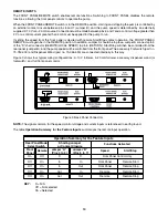
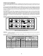
Figure 3 shows four typical wiring configurations: 2–10 V follower, 4–20 mA follower, accessory dispenser wand (or
footswitch), and full front panel control.
NOTE:
The signal common for the speed control voltage and current inputs is referenced to earth ground.
The table
Operation Summary for the Feature Inputs
summarizes the remote input operation.
Operation Summary for the Feature Inputs
Rear Panel Mode
Select Switch
Shorting Jumper
or Contact Closure
Functions Activated
Front
Panel
Remote
Jumper “A”
(Pins 4 to 5)
Jumper “B”
(Pins 6 to 7)
Speed
Start/Stop
On
Off
X
X
Front Panel Control Only
Off
On
In
In
Front Panel
Remote Start
Off
On
In
Out
Front Panel
Remote Stop
Off
On
Out
In
Remote
Remote Start
Off
On
Out
Out
Remote
Remote Stop
Figure 3. Back Panel Connectors
KEY:
X = N/A
Off = Not selected
On = Selected
Summary of Contents for VARISTALTIC KATE 72-620-000
Page 2: ...2 VARISTALTIC...


