11
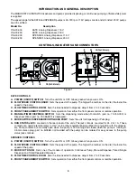
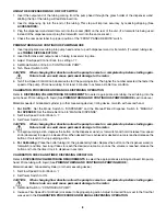
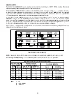
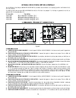
The START/STOP (pin 7) input and REMOTE/LOCAL SPEED (pin 4) input are digital inputs. They are internally pulled
up to +15 V with respect to logic common (RETURNS). They can alternately be driven with open collector logic. For
increased noise immunity, use of contact closures is recommended.
RUN STATUS JACK
The RUN STATUS jack is located on the back panel next to the FRONT PANEL/REMOTE switch. The jack provides a
normally open relay contact rated for 24 V at 1 A that closes whenever the pump is running. The contacts are made
between the tip and first barrel of the jack. The outermost contact of the jack is grounded. A mating 3.5 mm stereo plug
(part no. B-3968, not included with the pump) can be ordered for access to the RUN STATUS contacts.
MAINTENANCE
WARNING: Remove power from the pump before attempting any maintenance.
The speed control circuit has solid-state components that do not require service. An excessive load on the system may,
however, cause the fuse to blow. An indication of an excesive load is a switch that does not light with power applied to
the pump and when the ON-OFF switch is in the ON position. If this condition occurs, remove power from the unit and
remove the fuse from the fuse holder located on the rear of the pump. Replace the fuse with a fuse of the same type and
rating. This information is printed on the rear of the unit.
CAUTION:
Replace the fuse only with one of the same type and rating. The fuse rating and type are stated on
the rear panel.
Motor brush life depends on duty cycle and operating speed. Brushes should be inspected every six months or 2000
hours, whichever occurs first, or if erratic operation occurs. Replace when less than 7.6 mm (0.300 in) long.
These models are equipped with a toothed-belt that should be inspected for belt wear at the same interval as the
brushes. The presence of some belt dust at or inside the pump is normal and has no effect on the operation of the pump.
If the belt is slipping, adjust the tension by loosening the motor nuts that secure it to the motor bracket and swing the
motor away from the PC board. Once adjusted, tighten the nut. Do not over-tighten the belt, as this will cause excessive
drive belt wear, bearing wear and noise. Replace the belt if frayed or torn. (See
REPLACEMENT PARTS
.)
CLEANING
DANGER:
Remove power from the pump before any cleaning operation is started.
Keep the pump enclosure clean by using a mild detergent solution. Never immerse nor use excessive fluid when
cleaning the pump.
Summary of Contents for VARISTALTIC KATE 72-620-000
Page 2: ...2 VARISTALTIC...


