20.03.2009
3
Applicator unit function:
Segmental atomisers are driven by means of a rechargeable battery. Metering on all the units
mentioned is path-dependent and takes place by means of a wheel driven pump. Droplets are formed by the centrifugal force
of the rotating atomiser. The droplets are discharged downwards by the segmental atomiser through a continuously variable,
adjustable segment. Residual chemical in the tank not intended for application is approx. 50 ml. This residual fluid can be
refilled back into the original herbicide container.
Checking applicator unit function:
Chemical solutions may flow quicker or slower due to temperature fluctuations, for which
reason the flow rates in the metering table should be checked and corrected as necessary. This system is not suitable for the
application of water. Please use herbicides at all times for testing the spray process and calibrating the flow rate. Check the
rotating atomiser on a daily basis for cleanliness and free turning motion. Check the output volume from time to time
throughout the season.
Deployment of the applicator unit:
Adjust the height of the spray hood in such a manner that it is as close to the ground as
possible - if it is set too high, the risk of spray driftage exists. During operation, chemical fluid will collect in the segmental
atomiser reservoir and will continue to drip for approx. 30 seconds after the shut-off valve has been closed if the unit is tilted.
In order to avoid damage to cultivated plants due to dripping, we recommend closing the shut-off valve at the end of a row, for
example, then folding the spray hood upwards and waiting approx. 30 seconds until the reservoir has emptied.
Spray width
•
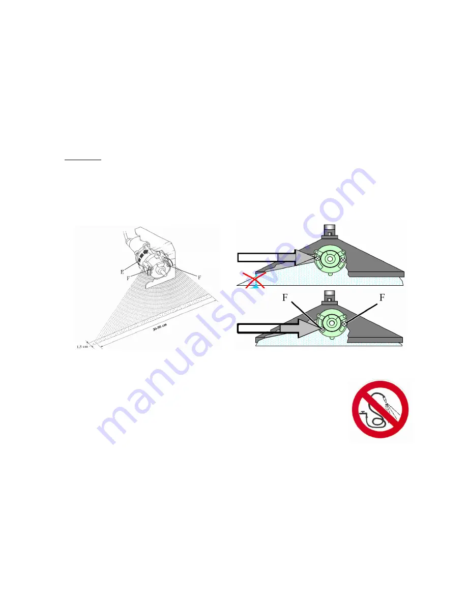
Place an underlay (cardboard or paper) on the ground and prop up the unit on stands.
•
Actuate the switch button on the powerpack while simultaneously turning the wheel and appraising the spray width
obtained, initially at one location. The spray width must be set in such a manner that the droplets are discharged over the
entire width of the spray hood. The optimal spray width under standard operating conditions is set by the manufacturer.
•
Compensate for deviations is possible by loosening screw (F) and sliding the width adjustment on the atomiser
(see drawing).
•
Further details regarding operating width adjustment can be found on the respective pages for the individual applicator
units.
Cleaning
Do not clean the applicator unit with a high-pressure sprayer or with an intense water jet spray
.
Cleaning during the season:
During short work breaks (a few hours), herbicide can remain
in the system as long as the shut-off valve remains closed. After work completion: before
cleaning, refill the chemical solution into its original container. Open the shut-off and set the
metering pump to maximum. Fill the chemical tank halfway with water, then, with the unit
positioned, turn the wheel smoothly 50 x and allow the fluid to drain into a collector tank or,
operating the unit for approx. 100 m, apply the cleaning fluid to the already treated surface.
Remove any remaining water from the tank and turn the wheel 50 x once again until the
system is completely empty.
Cleaning at the end of the season:
Rinse the unit with warm water as described above. Additionally: Unscrew filter and
clean screen as necessary. The spray hood and the atomiser housing can be cleaned with a moist cloth, except the atomiser
disc in order to avoid damage. With heavy contamination, the atomiser housing should be unscrewed to remove
contaminants and plant parts. Connect the unit to the charging device (see below).
Charging the applicator unit and care of the accumulator
The applicator unit is outfitted with an automatic charging device. Trickle charging is possible.
In order to recharge a completely empty battery up to full capacity, approx. 16 hours charging time is required.
The battery should be recharged immediately after usage.
Battery charging
Minimum charging time
Time interval
Fully discharged
16 hrs.
immediately
Short-term usage
6 hrs.
immediately
Storage without usage
( 2 hrs. 1 x per month )
or permanent charge
With a fully loaded battery, units with one atomiser can be deployed for 16 hours, while units with 2 atomisers can be
deployed for approx. 8 hours.
INCORRECT
CORRECT


