background image

21

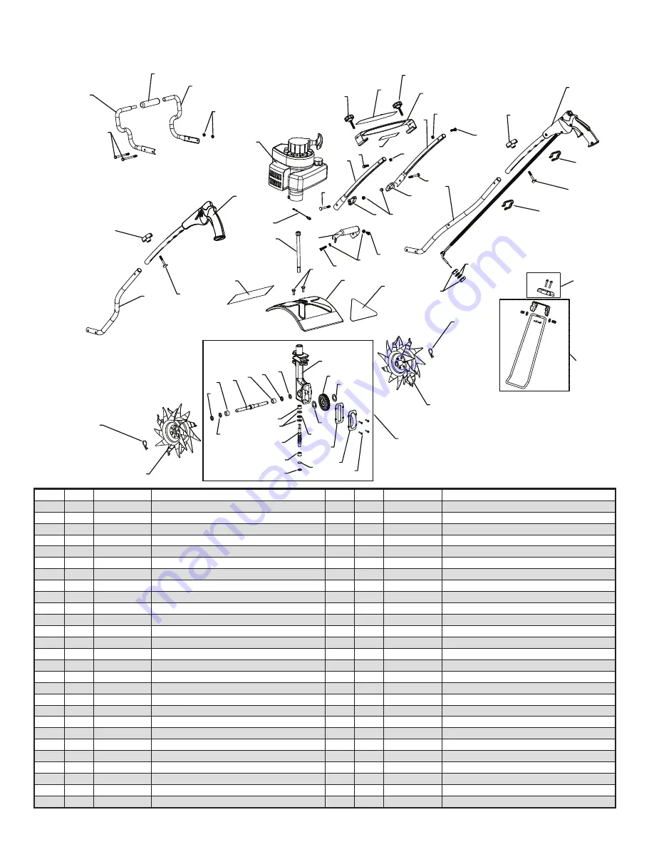
MANTIS TILLER ASSEMBLY

7

44

52

25

45

26

40


31

32

36

38

41

33

35

36

34

37

38

29

27

37

28

30

35

24

23

39

41

17

53

48

21

16

53

19

50

46

22

49

20

48

15

49

2

42

53

47

49

4

48

14

11

10

9

17

51

48

6

42

19

13

13

3

8

49

53

1


43

12

18

54

55

ITEM

QTY

PART #

DESCRIPTION

ITEM

QTY

PART # 

DESCRIPTION

430003 

Trigger Handle Assembly, 2 Cycle Engine, Right

29 

424 

Worm Thrust Bearing

1

430006 

Handle Assembly, Left

30

1

422

Worm Shaft

430053 

Middle Handle W/plug, Right

31 

426 

Worm Disk

430052 

Middle Handle W/plug, Left

32 

428

Retaining Ring

430051

Lower Handle W/plug, Right

33 

429 

Worm Gear

430050 

Lower Handle W/plug, Left

34 

431 

Tine Shaft

430021 

Handle Brace

35 

430 

Worm Gear Thrust Washer

430056

Label, Handle Brace

36 

432 

Worm Gear Bearing

10 

430023 

Loop Handle Right Half

37 

434 

Bearing Seal

11 

430022 

Loop Handle Left Half

38 

435 

Bearing Seal Retainer

12 

4078 

M6 Internal Lock Washer

39 

438RA 

Tine Assembly, Right

13 

478

Throttle Clip

40 

1

438LA 

Tine Assembly, Left

14 

2

430025 

Foam Grip

41 

418-1 

Tine Retaining Pin

15 

430049 

Carry Handle With Grip

42 

430039 

Carriage Bolt 1/4-20 X 2.25"

16 

2

4049 

Bolt 1/4-20 X 3.25"

43 

430042 

Ground Wire Jumper, 2 Cycle Engine

17 

430038 

Knob, 1/4-20 X1.5 Male

44 

400630 

Triangle Warning Label (2 Cycle Engine)

18 

4079 

M6 Jam Nut

45 

458 

Roller Bearing (closed end)

19 

2

430048

Curved Head Bolt, 1/4-20 X2"

46 

430058 

Mantis Logo Label

20 

465 

Fender Guard

47 

395 

Acorn Nut

21 

1

400904 

Engine Assembly Sv-5ci/2

48 

972 

1/4-20 Two-way Lock Nut

22 

1

468 

Drive Shaft

49 

144-2 

1/4-20 X 1.125 Hex Head Cap Screw

23 

466 

Worm Gear Housing

50 

140 

Bolt 1/4-20x3/8" Long

24 

436

Gasket

51

430057 

Warning Label

25 

437A 

Gear Housing Cover

52 

400010 

Transmission Assembly*

26 

651

#8 Self Tapping Screw

53 

400523 

Knob, Two Prongs, Female

27 

1

423 

Roller Bearing

54 

410158 

Kickstand, Stand Assembly

28 

425 

Worm Bearing Race

55 

430037 

Kickstand, Bracket And Hardware

* Includes Key #22

*

401775 Deluxe 2C Tiller-Cult Manual_Tiller Manual  8/8/11  8:08 AM  Page 21

Summary of Contents for 7234 DELUXE

Page 1: ...ELUXE 2 CYCLE TILLER CULTIVATOR OWNER S MANUAL IMPORTANT ASSEMBLY INSTRUCTIONS START ON PAGE 5 PLEASE REVIEW THE WARNING SAFETY INFORMATION ON PAGES 3 4 AND THE ASSEMBLY INSTRUCTIONS BEFORE UNPACKING THE BOX ...

Page 2: ...tillers your MANTIS Tiller weighs only 25 pounds So it lifts easily handles smoothly tills and weeds precisely And unlike other small tillers it features serpentine tines that churn soil up to ten inches deep It creates a soft smooth seed bed even in problem soil Once you know how to use your tiller correctly we guarantee you ll love it So first please read this manual It shows step by step how to...

Page 3: ...LACE DO NOT CARRY THE TILLER IN THIS POSITION An important part of the safety system incorporated in this tiller are the warning and information decals found on various parts of the tiller These decals must be replaced in time due to abrasion etc It is your responsibility to replace these decals when they become hard to read The location and part numbers P N of these decals are illustrated on Page...

Page 4: ...ely before starting engine Don t operate your tiller if there is an accumulation of debris around the muffler and cooling fins Don t touch hot mufflers cylinders or cooling fins as contact may cause serious burns Don t change the engine governor setting or over speed the engine VI Engine Fuel Warnings Do s VII Engine Fuel Warnings Don ts IV Warnings Do s Read and understand the owner s manual Pay ...

Page 5: ... flat side Open bottom of the box and lift box flaps up Return box to the standing position Do not remove upper right throttle handle assembly and engine portion of the tiller in this step Helpful Hint 1 Keep like items together Helpful Hint 2 CAUTION When removing tine box handle the box with extreme caution Tines are sharp and can come through the cardboard box 5 Ratchet 7 16 Wrench 3 8 Wrench E...

Page 6: ...cap screws H 1 4 20 Two way lock nut B C Loop Handle G 3 25 Bolts D Loop handle grip I Carry Handle w grip E F Lower Handle A Transmission and Engine Assembly E Right B Right F Left C Left Key Qty Part No Description H 2 972 1 4 20 Two way lock nut J 2 144 2 1 4 20 x 1 1 8 Hex head cap screws K 1 430003 Trigger handle assembly right L 1 430006 Handle assembly left M 1 430053 Middle handle right N ...

Page 7: ...ne side only at a time Helpful Hint Finger tight is one half to one full turn Helpful Hint Keep throttle cable out of the way Helpful Hint Hold bolts on right side as you put left side onto the bolts Helpful Hint D D B B C B C D F E E B C Loop Handle B Right F C Left 1 A K 1 D Loop handle grip I C H 1 4 20 Two way lock nut L T E A C L T K G 3 25 Bolts A L E F Lower Handle E Right B F Left C 1 A K ...

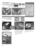
Page 8: ...rtion of lower handle with the stamped arrow pointing up Fully assembled lower portion of the tiller Place kickstand below lower handle so the holes of the kickstand line up with the kickstand brace Z Place 2 1 4 20 serrated flange screws Za through the holes in the top brace and tread into kickstand Y Tighten kickstand Y and kickstand brace Z with 2 1 4 20 serrated flange screws Za using 3 8 wren...

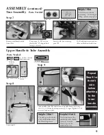
Page 9: ... lower handle assembly Remove cardboard cradle from tiller Take middle tube M and attach to handle brace O using 1 4 20 x 1 1 8 hex head cap screws J Finger Tighten 1 4 20 two way lock nuts H Step 8 Step 9 Layout parts Place tines V W on tine shaft with D shaped hole facing outward Secure with tine retaining pins X Put Kickstand down and rest tiller on kickstand and tines M M N O K L Parts Needed ...

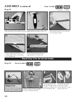
Page 10: ...ts R Do not tighten at this time Thread two prong knob Q onto exposed bolt S two full turns Place curved head S bolt into slot Curved head bolt S should come out of middle tube Slide curved head bolt S into bottom slit of the upper handle Repeat Step 10 for the left side handle Rest the handles on the ground to help in the assembly process Helpful Hint K S S Q K M O O S Curved Head Bolts Q Knobs T...

Page 11: ...nt Q T Acorn Nuts Parts Needed P Knob 1 4 20 x 1 5 male Parts Needed Suggested Height Settings 12A 13A 13B 12B Fully tighten the 2 two prong knobs Q shown above Fully tighten nuts and bolts installed in Step 9 located underneath handle brace 13C 12C IMPORTANT NOTE Be sure you have proper throttle movements and that the throttle cable is not wrapped or twisted around the handle bar Hold down the lo...

Page 12: ... NOT APPROVED FOR USE IN ECHO 2 STROKE GASOLINE ENGINES USE OF ALTERNATIVE FUELS MAY CAUSE PERFORMANCE PROBLEMS LOSS OF POWER OVERHEATING FUEL VAPOR LOCK AND UNINTENDED MACHINE OPERATION INCLUDING BUT NOT LIMITED TO IMPROPER CLUTCH ENGAGEMENT ALTERNATIVE FUELS MAY ALSO CAUSE PREMATURE DETERIORATION OF FUEL LINES GASKETS CARBURETORS AND OTHER ENGINE COMPONENTS To Start Your Tiller for the First Tim...

Page 13: ...E PUT THE TILLER DOWN AND PULL THE CHOKE BUTTON OUT TO COLD START CLOSED POSITION CHECK AND RETURN IGNITION SWITCH TO ON POSITION BEFORE STARTING ENGINE AGAIN Picture 1 Additional Information to increase the engine speed and engage the tines NOTE Step 6 must be repeated each time your tiller trigger is released WHAT TO DO JUST IN CASE If you follow the normal starting procedure you should have no ...

Page 14: ...your tiller is running you can walk it to your garden Just hold down the throttle lock out lever and squeeze the throttle trigger gently and let the tiller tip toe across your yard on its tines It won t hurt your lawn Carry It Make sure the engine is off Then use one hand to grasp the front loop handle Use the other hand to hold the carry handle Picture 1 Then lift your tiller and carry it to your...

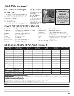
Page 15: ...r discharge ignition type Starter Automatic rewind with power spring assist Oil Designated two stroke air cooled engine oil Fuel Tank Capacity 0 5 lit 17 0 oz ENGINE SPECIFICATIONS SERVICE MAINTENANCE GUIDE COMPONENT SYSTEM MAINTENANCE PROCEDURE REQ D SKILL LEVEL DAILY OR BEFORE USE EVERY REFUEL 3 MONTHS OR 90 HOURS YEARLY 600 HOURS Air Filter Inspect Clean 1 I C Choke Shutter Inspect Clean 1 I C ...

Page 16: ...our MANTIS Tiller Will Weed Between Narrow Rows Your MANTIS Tiller is a precision weeder that easily fits in tight places So don t be afraid to weed anywhere between plants and shrubs in corners against fences on raised beds in wide rows even in very narrow rows So you can run it in a tightly planted garden without damaging your delicate plants That s good news for suburban gardeners who often hav...

Page 17: ... inside the rim that holds the filter in place Installing the filter incorrectly will cause engine damage and void the warranty Fit the cover back over the air cleaner Again make sure to clear the choke button 8 Tighten the wing nut to secure the cover Note Please check the lip on the Air Cleaner Cover If the lip is chipped or cracked it should be replaced This will prevent dirt from being ingeste...

Page 18: ...e sure the hex head lines up with the clutch drum inside the clutch case Then put the engine back on the worm gear housing If you ve followed these steps properly there will be no gap between the clutch case and the worm gear housing Picture 2 Make sure you tighten the flange bolt Exhaust Port Muffler Cleaning Tools required 4mm Hex wrench Wood or plastic scraper Parts Required As needed Heat Shie...

Page 19: ...the handles follow these easy steps Loosen the handle knobs 53 fold the handles forward see picture 1 inset Tighten knob securely Your handles are now folded and ready to store in a smaller area 15 Do you have fuel left over from last season Dispose of it properly Buy fresh oil and gasoline next season How to Prepare Your MANTIS Tiller for Restarting Unfold the handles into an upright or extended ...

Page 20: ...ion and place it under the cylinder cover in the small pocket in the cylinder cover 5 There is black smoke coming from exhaust The muffler screen is clogged Clean carbon from muffler screen page 13 6 Engine misses Dirt in fuel line or carburetor Carburetor improperly adjusted Spark plug fouled broken or incorrect gap setting Weak or intermittent spark at spark plug Remove and clean See Carburetor ...

Page 21: ...ainer 12 2 4078 M6 Internal Lock Washer 39 1 438RA Tine Assembly Right 13 2 478 Throttle Clip 40 1 438LA Tine Assembly Left 14 2 430025 Foam Grip 41 2 418 1 Tine Retaining Pin 15 1 430049 Carry Handle With Grip 42 2 430039 Carriage Bolt 1 4 20 X 2 25 16 2 4049 Bolt 1 4 20 X 3 25 43 1 430042 Ground Wire Jumper 2 Cycle Engine 17 2 430038 Knob 1 4 20 X1 5 Male 44 1 400630 Triangle Warning Label 2 Cyc...

Page 22: ...OTTLE A17 12532715130 1 CLIP THROTTLE SHAFT A18 12532412820 1 COVER FUEL PUMP A19 12533406960 1 SCREW IDLE ADJUST A20 12533306960 1 SPRING IDLE ADJUST A21 12531012820 2 SCREW FUEL PUMP COVER A22 12533942030 1 SCREW METERING LEVER PIN A23 12530013120 1 REPAIR KIT INCLUDES ITEMS 24 33 A24 1 DIAPHRAGM METERING A25 1 GASKET METERING DIAPHRAGM A26 1 PIN METERING LEVER A27 1 LEVER METERING A28 1 VALVE I...

Page 23: ...CLUDED IN GASKET KIT PAGE 19 1 3 2 5 4 6 7 9 8 10 11 13 14 15 16 17 9 12 8 7 6 4 3 2 1 5 MUFFLER EXPLOSION C B1 B3 B5 B2 B4 B6 B7 B8 B9 B11 B10 B12 B13 B16 B14 B15 B17 C9 C8 C4 C3 C2 C1 C5 C6 C7 ITEM PART QTY DESCRIPTION REMARKS D1 811025 1 STARTER ASY INCLUDES ITEMS 2 8 D9 90023804016 4 SCREW 4X16 D10 17720212220 1 STARTER PAWL ASY INCLUDES ITEMS 11 12 D11 17721844330 2 PAWL STARTER D12 177234122...

Page 24: ...ITEMS 6 9 E6 A101000090 1 RING PISTON E7 10001311520 1 PIN PISTON E8 10001504630 2 CIRCLIP PISTON PIN E9 10001411520 2 SPACER PISTON PIN E10 A011000390 1 CRANKSHAFT ASY INCLUDES ITEM 11 E11 V553000060 1 BEARING NEEDLE E12 10020411521 1 CRANKCASE KIT INCLUDES ITEMS 13 17 E13 10021242031 2 OIL SEAL E14 V622000020 2 DOWEL PIN 4X7 8MM E15 10024242030 1 GASKET CRANKCASE1 E16 9403536201 2 BEARING BALL 6...

Page 25: ...ned built and equipped to conform with applicable EPA and C A R B emissions standards and that your equipment SORE is free from defects in material and workmanship that would cause it to fail to conform with applicable requirements for 2 years or the length of the ECHO Inc warranty whichever is longer The warranty period begins on the date the product is purchased by an end user HOW WILL A COVERED...

Page 26: ...ts and service This limited warranty shall not be effective if your Mantis tiller has been subjected to negligence or has been repaired or altered by anyone other than an authorized dealer or authorized service center You must maintain your MANTIS TILLER by following the maintenance procedures described in the owner s manual Such routine maintenance whether performed by you or a dealer is at your ...

Reviews: