DMJOIL101EN - v1
VISIO L1H OPERATOR -
INSTALLATION MANUAL
16
6.2
6.1
6.3
6.4
Fig.
Fig.
Fig.
Fig.
Fig.
6.5
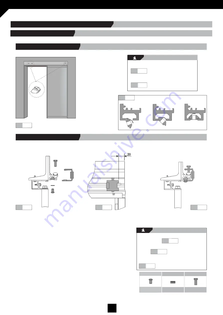
Insert 4 nuts distributed in the AT as shown in
the diagram.
Insert the nuts in the bottom channel of the main
profile.
Introduce lateral end stops and screws/nuts
into main profile.
6.3
Position stops at the two ends of the main
profile.
6.4
Screw to the nut inside the channel, and tighten
the screw over the track rail.
6.5
DIN7380 6x10
DIN6798 M-6
DIN933 6x12
Nuts & bolts
Nuts & bolts
Nuts & bolts
Fig.
Fig.
Fig.
6.1.2 Lateral stops assembly.
Fig.
Fig.
6.1
6.2
6.1.1 Insert nuts into profile.
6.1 LATERAL STOPS ASSEMBLY
6. LATERAL STOPS / LOCK ASSEMBLY


