DMJOIC201EN - v2
VISIO C2H OPERATOR -
INSTALLATION MANUAL
26
9.2
i
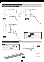
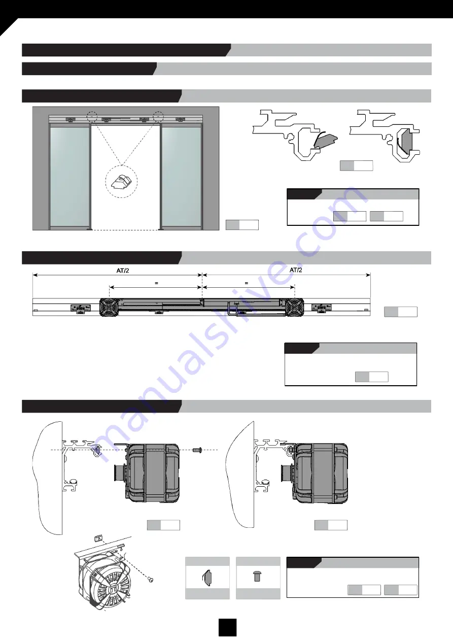
Insert nuts in main profile as shown in
the diagrams.
9.1
9.2
9.1
Fig.
Fig.
Fig.
Fig.
9.3
i
Position the drive unit so that the two
motors are the same distance from the
centre of AT.
9.3
Fig.
Fig.
9.4
9.5
i
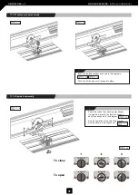
Screw the drive unit to the main profile as
shown in the diagrams.
9.4
9.5
DIN7380 6x14
Spring Nut M6
Fig.
Fig.
Nuts & bolts
Nuts & bolts
Fig.
Fig.
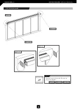
9.1 DRIVE UNIT ASSEMBLY
9.1.1 Insert nuts in main profile.
9. DRIVE UNIT / BELT ANCHOR ASSEMBLY
9.1.2 Placement of drive unit.
9.1.3 Screw in the drive unit.


