DMJOIC201EN - v2
VISIO C2H OPERATOR -
INSTALLATION MANUAL
28
i
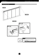
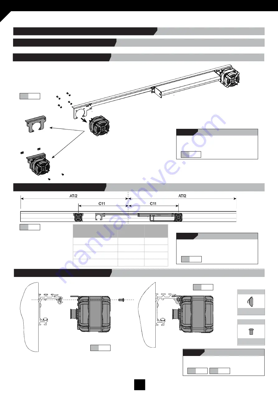
Screw the drive unit to the main profile as
shown in the diagrams.
Fig.
9.11
Fig.
9.10
Fig.
9.10
Nuts & bolts
DIN7380 6x14
Nuts & bolts
Spring Nut M6
Fig.
9.11
i
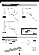
Position the drive unit so that the two
motors are the same distance from the
centre of AT.
Fig.
9.9
Fig.
9.9
i
Unscrew the left hand motor from the drive
unit and screw it onto the extension plate,
as shown in the diagram.
Fig.
9.8
Fig.
9.8
PL
C11
Length
of Belt*
2001 < PL < 2250
742
3050
2251 < PL< 2500
867
3550
2501 < PL < 2750
992
4050
2751 < PL < 3000
1117
4550
9a.1.1 Drive unit pre-assembly.
9a.1 DRIVE UNIT EXTENSION ASSEMBLY
9a. ANEXO: DRIVE UNIT EXTENSION ASSEMBLY (PL > 2000mm)
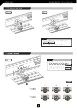
9a.1.3 Screw in drive unit.
9a.1.2 Placement of drive unit.


