30
Montage- und Betriebsanleitung
Installation and Operating Instructions
DE
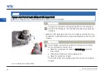
Schrauben Sie in den abgekühlten Werkzeughalter an „Pos. 2“ die Ge-
windestifte mit Schraubensicherung (Klebstoff) mittelfest ein (siehe
Abb.
15: Kühlmittelzuführung FFoorrm
m AAFF//JJFF).
Entfernen Sie eventuelle Klebstoffreste.
Kontrollieren Sie nach der Aushärtezeit des Klebers die Gewindestifte auf
festen Sitz und wuchten Sie den Werkzeughalter neu.
Verwenden Sie für die maschinenseitige Abdichtung des Werkzeughalters
einen Anzugbolzen mit Kühlmittelbohrung.
Kühlmittelzuführung FFoorrm
m AAFF//JJFF
EERRG
GEEBBN
NIISS
Die Kühlmittelzuführung ist nach FFoorrm
m AAFF//JJFF umgestellt.
55..33..33
N
Naacchh FFoorrm
m AADD bbzzw
w.. JJDD uum
msstteelllleenn
Umstellung der Kühlmittelzuführung von der Form AF nach Form AD.
W
WAARRN
NU
UN
NG
G
VVeerrbbrreennnnuunnggssggeeffaahhrr dduurrcchh hheeiißßeenn G
Geew
wiinnddeessttiiffttbbeerreeiicchh!!
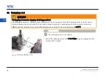
Beim Erwärmen und Herausdrehen der Gewindestifte können schwere Verbrennungen und Verletzungen ent-
stehen.
Beim Erwärmen und Herausdrehen der Gewindestifte immer ISO-Schutzhandschuhe tragen.
Nach dem Erwärmen warten, bis der Gewindestiftbereich abgekühlt ist.
Montage- und Betriebsanleitung
Installation and Operating Instructions
45
EN
44..33
TToooollss aanndd m
maatteerriiaallss rreeqquuiirreedd
•
Hex-wrench for the stop screw for axial or radial tool length adjustment.
•
Hex-wrench for the clamping screw.
44..44
TTeecchhnniiccaall ddaattaa
W
WAARRN
NIIN
NG
G
FFaaiilluurree ttoo oobbsseerrvvee tthhee tteecchhnniiccaall ddaattaa aanndd m
maaxx.. ooppeerraattiinngg ssppeeeeddss!!
Failure to observe the technical data can result in serious injury to the operator and in machine damage.
Observe the technical data given in
section 4.4.
During clamping, screw in the clamping screw up to the stop, observing the specified minimum number of rotations.
Observe the prescribed values for the minimum clamping depth.
Observe the prescribed operating speed limits for the machine-side connection and the selected tool.
Observe the maximum load limit for the machine-side connection in accordance with e.g. VDMA 34181 and the
selected tool.
If irregularities occur during operation, do not use the HPH clamping chuck further for safety reasons and send it to
WTE for inspection or repair.
44
Montage- und Betriebsanleitung
Installation and Operating Instructions
EN
44..22
M
Maarrkkiinngg ooff tthhee aaccttuuaattiinngg eelleem
meennttss
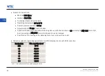
Marking for checking of the clamping force: Three possible positions on the clamping chuck
KKeeyy
1 |
++ Clamp tool (in clockwise direction)
2 |
-- Unclamp tool (in anticlockwise direction)
Indication of the direction of rotation for clamping and unclamping the tool
Montage- und Betriebsanleitung
Installation and Operating Instructions
44
EN


