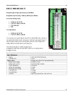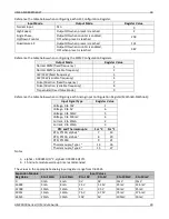
I/O Expansion Module Overview
17
HMC3000 Series I/O Module Guide
17
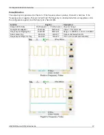
Pulse/Direction
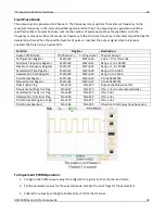
The output signal is generated on Channel 1. If the frequency value is positive, Channel 2 is held low. If the
frequency value is negative, Channel 2 is held high. The frequency can be adjusted while running (place an 8 in
the configuration register), and the Duty Cycle is fixed at 50%.
Function
Register
Description
Output, PWM Pulse
Y0 (Channel 1)
Y1 (Channel 2)
Physical Output
Configuration Register
MWnn24
MWnn30
Value = 7 for this mode
Frequency Setting Register
MWnn25
MWnn31
Range = -100000 to -1 and 1 to 100000
Pulse Enable Flag
Mnn576
Mnn577
Output enabled when ON
Frequency Setting Error Flag
Mnn467
Mnn472
ON = error (resets automatically)
Summary of Contents for HMC3-M0808P0401T
Page 26: ...HMC3 M0808P0401T 26 HMC3000 Series I O Module Guide 26...
Page 34: ...HMC3 M0808Y0401T 34 HMC3000 Series I O Module Guide 34...
Page 41: ...HMC3 M1212P0200 41 HMC3000 Series I O Module Guide 41 HSC Quadrature...
Page 48: ...HMC3 M1212Y0200 48 HMC3000 Series I O Module Guide 48 HSC Quadrature...
Page 56: ...HMC3 M1210P0201 56 HMC3000 Series I O Module Guide 56...
Page 67: ...HMC3 M1614Y 67 HMC3000 Series I O Module Guide 67 HSC Single Phase Down Counter HSC Quadrature...
Page 71: ...HMC3 M1616P 71 HMC3000 Series I O Module Guide 71 HSC Single Phase Down Counter HSC Quadrature...
Page 72: ...HMC3 M1616P 72 HMC3000 Series I O Module Guide 72...


