Model HMC7-MIO-08
Phone: 425/745-3229 • Fax: 425/745-3429 • Email: maple@maplesystems.com • www.maplesystems.com
Doc. No. 1011-0715
Page 2 of 2
Rev. 05, 05/18/2016
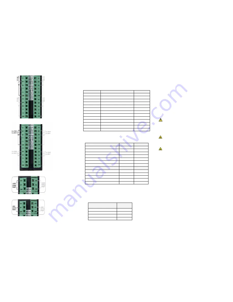
Connection for RTD inputs:
Connection for mV/thermocouple inputs:
Connection for voltage outputs:
Connection for current outputs:
Configuration:
Use MAPware-7000 to assign input (XW) output (YW) and
configuration (MW) memory addresses to the module.
These addresses are created according to the slot location of
the module, where nn refers to the slot number (ex. 01… 05):
Register
Description
Access
XWnn00
Input Channel 1 Data
Read Only
XWnn02
Input Channel 2 Data
Read Only
XWnn04
Input Channel 3 Data
Read Only
XWnn06
Input Channel 4 Data
Read Only
YWnn00
Output Channel 1 Data
Read/Write
YWnn01
Output Channel 2 Data
Read/Write
MWnn00
Input Channel 1 Config. Reg.
Read/Write
MWnn01
Input Channel 2 Config. Reg.
Read/Write
MWnn02
Input Channel 3 Config. Reg.
Read/Write
MWnn03
Input Channel 4 Config. Reg.
Read/Write
MWnn04
Output Channel 1 Config. Reg.
Read/Write
MWnn05
Output Channel 2 Config. Reg.
Read/Write
MWnn10
Analog Input Error Reg.
Read/Write
Reference the table below when configuring each Input
Configuration Register (MWnn00 – MWnn03)
Input Channel Signal Type
Value
Value
Voltage 0 to 10V
1
-
Voltage, 0 to 5V
6
-
Voltage, -10 to +10
18
-
Voltage, 0 to 50 mV
5
-
Voltage, 0 to 100mV
4
-
Current, 4 to 20mA
2
-
Current, 0 to 20mA
3
-
RTD and Thermocouple
For °C
For °F
RTD, PT100, alpha1
1
7
19
RTD, PT100, alpha2
1
8
20
RTD, PT1000
9
21
Thermocouple Type J
2
14
26
Thermocouple Type K
2
15
27
1.
alpha1= 0.00385
Ω
/
Ω
/
°
C, alpha2=0.003926
Ω
/
Ω
/
°
C
2.
15-minute module warm-up time recommended
Reference the table below when configuring each
Output Configuration Register (MWnn04 – MWnn05)
Output Channel Signal
Type
Value
Voltage, 0 to 10V
2
Voltage, 0 to 5V
1
Current, 4 to 20mA
5
Current, 0 to 20mA
6
Additional Resources:
Detailed instructions on the operation and installation of the
HMC7000 Series are available in the HMC7000 Programming
Manual that is included with the MAPware-7000 configuration
software. MAPware-7000 also includes help files, which
provide detailed information on using the configuration
software.
WARNING: DO NOT REMOVE OR REPLACE WHILE CIRCUIT
IS LIVE UNLESS THE AREA IS KNOWN TO BE FREE OF
IGNITIBLE CONCENTRATIONS OF FLAMMABLE SUBSTANCES.
This equipment is suitable for use in Class I, Division 2, Groups
A, B, C and D or non-hazardous locations only.
WARNING – EXPLOSION HAZARD – Do not disconnect
equipment unless power has been removed or the area is
known to be non-hazardous.
WARNING – EXPLOSION HAZARD - Substitution of
components may impair suitability for Class I, Division 2.
It is recommended that the user periodically inspect the sealed
devices used, check for any degradation of properties, and
replace as necessary.
For Technical Support:
Please contact Maple Systems if you have any questions
regarding this product. We ask that you provide us with the
unit serial number and firmware revision number written on
the product label of the unit.
Maple Systems Inc.
808 134
th
St. SW, STE 120
Everett, WA 98204
Tel: 425-745-3229
Fax: 425-745-3429
Email: support@maplesystems.com
Website: www.maplesystems.com


