3.5. Connect OIT to Power
WARNING
Use only with Class 2 power source limited to 30 VDC open
circuit and 8A short circuit.
The power cable for the OIT should be 18AWG 2-conductor wire with a shield wire
and protective shield foil. Maple Systems sells cable P/N 6030-0009 by the foot for
user-built power cables.
STEPS
1. The power cable should not be any longer than necessary. Prepare the cable
as follows:
a) Cut the power cable to the appropriate length.
b) Strip the cable shield back to expose the two insulated wires and the bare
shield wire on both ends of the power cable.
c) Strip the insulation from the two insulated wires. For the OIT end, this
is 0.27 inch (7 mm).
1010-0104, REV 03
12
OIT3185A/4185A
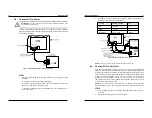
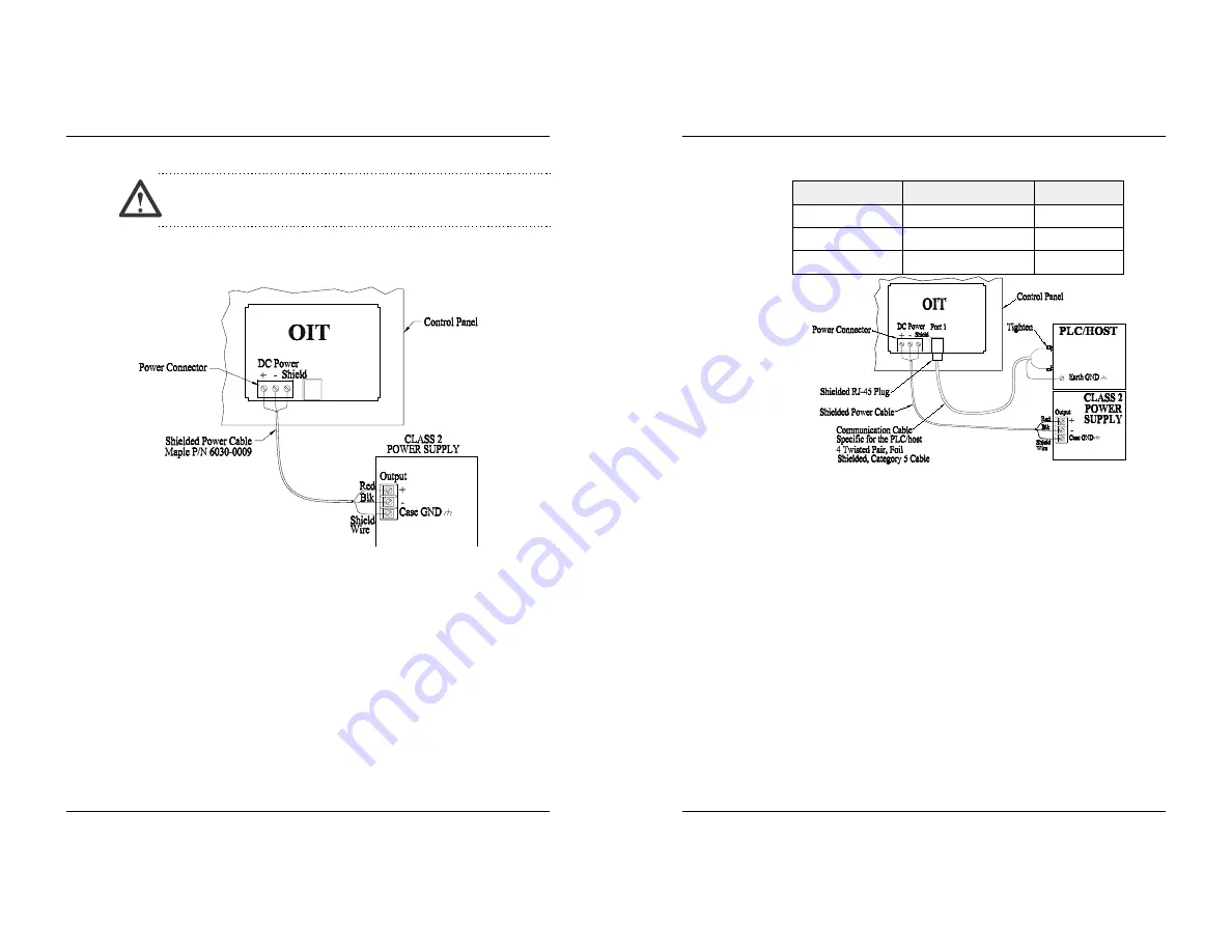
Figure 4 OIT3185/4185 Power Supply Connection
2. Install the wires into the Class 2 power supply as follows (colors shown are
for Maple Systems Cable P/N 6030-0009):
COLOR
POWER SUPPLY
OIT
Red
+ Output
(+)
Black
- Output
(-)
Shield Wire
Case Ground
Shield
NOTE:
The power connector on the OIT has M3 slotted screws.
3.6. Connect OIT to PLC/Host
Each PLC/host supported by Maple Systems has its own wiring requirements.
Maple Systems offers pre-constructed OIT-to-PLC communication cables for
most PLCs. Most cables are available for same day shipment from Maple Systems.
They are built and tested for high reliability and are strongly recommended. Maple
Systems also builds custom cables—contact the factory for information.
Components and instructions necessary to construct your own OIT-to-PLC
communications cables are also available. Refer to Maple Systems’ Price List or
web site (www.maple-systems.com).
NOTE:
Refer to the ASCII Slave Protocol Guide or the STEP1 Protocol Operation
Manual for information on constructing OIT-to-ASCII host communication cables.
STEPS
1. Connect the RJ-45 plug end of the communication cable into the serial port
on the OIT.
2. Ensure that the locking tab has secured the plug.
1010-0104, REV 03
INSTALLATION MANUAL
13
Figure 5 OIT3185/4185 PLC Connection


