5. Custom Keypad Slide-In Legends
The OIT3185 and OIT4185 have a graphic overlay covering the keypad. This
overlay contains a clear window that allows you to insert your own legend to
customize the keypad’s text, colors, and graphics. This legend can be
inexpensively made and is environmentally sealed when installed.
The slide-in legend can be made on any non-glossy stock between 0.004 inches (0.1
mm) and 0.008 inches (0.2 mm) thick by using any of the following methods:
• Photocopy one of the predefined keypad templates.
• Photocopy the blank legend and hand illustrate.
• Use the dimensions to create a computer generated legend.
• Use our Legend Generator software to create a computer generated legend.
Available from out web site at
www.maple-systems.com/tech.htm
.
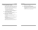
5.1. Predefined Keypad Templates
If you have chosen one of the predefined keypad templates in OITware-200, you
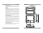
can photocopy the corresponding slide-in legend from Figure 8.
5.2. Blank Legend for Photocopying
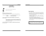
The blank legend in Figure 9 can be photocopied and hand illustrated.
When photocopying:
• Use only non-glossy stock which is 0.004 - 0.008 inches (0.1 - 0.2 mm) thick.
• Check photocopy accuracy with the printed check dimension.
When illustrating:
• Use the tick marks to locate the switch centers. Refer to the computer generated
legend dimensions if unsure.
NOTE:
Pressing the center of the switch is critical for switch actuation.
• Recommended key size is 0.500 inches [12.7 mm] square.
• Background colors should extend to the solid lines.
• All text and graphics should be 0.07 inches [1.78 mm] within the solid lines.
NOTE:
Do not affix anything to the legend using glue, tape, stickers, etc.
16
OIT3185A/4185A
1010-0104, REV 03
• Keep the lengths of the OIT cables as short as possible. Do not coil excess cable
and place it next to AC powered equipment.
2.4. Other Steps to Improve Noise Immunity
• Always install the OIT’s rear cover. This provides a shield against electrical
noise which can be generated in the control panel by relays, motors, power lines,
and/or high frequency equipment. Ensure that all rear cover mounting screws
are properly secured.
• Any equipment used in the enclosure that operates at high frequency or high
current levels can be covered with a grounded metal shield.
INSTALLATION MANUAL
9
1010-0104, REV 03


