STEPS
1. Remove the four #8-32UNC mounting nuts from the rear of the OIT using
an 11/32 inch socket wrench or nut driver.
2. Remove the bezel (frame) as shown in Figure 5A.
3. Tilt the top of the OIT towards you, approximately 15-20°, and gently place
it against the panel cutout as shown in Figure 5B.
4. Gently slide the OIT downward until it is resting against the cutout.
5. Replace the bezel (frame).
6. Secure the OIT by re-installing the four #8-32UNC mounting nuts on the
rear of the OIT using an 11/32 inch socket wrench or nut driver.
CAUTION:
Do not torque the 4 mounting nuts to over 30 pound-inches. Over
torquing can strip the threads. The unit is properly installed when the bezel first
touches the control panel. Additional tightening will not improve the seal.
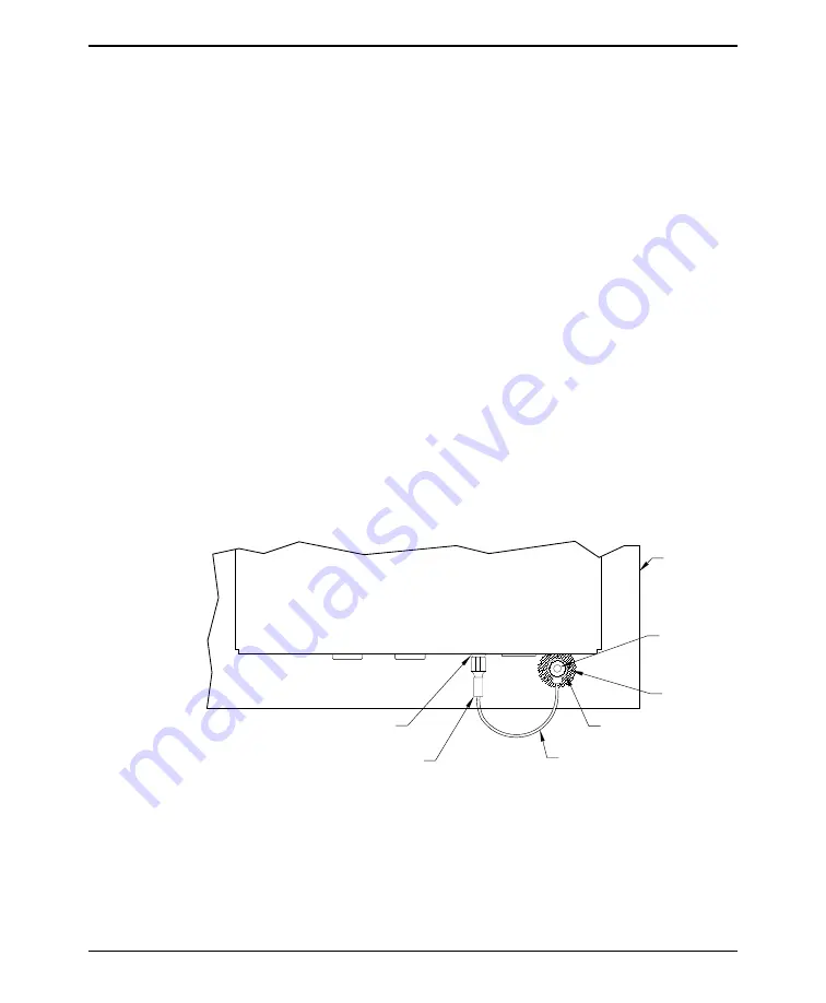
2.4. Connect OIT Chassis Ground to Control Panel
The green ground wire assembly, supplied with the OIT, must be installed as shown.
This provides a good earth ground connection to the OIT’s bezel and rear cover.
If your control panel is metal, be sure it is grounded. If it is a non-conductive
material such as plastic, run an additional ground from either the dual-tab lug on the
OIT or the mounting stud (shown) to a good ground point. Use a braided grounding
strap that is as short as practical.
STEPS
1. Remove the mounting nut from the lower right hand stud, as viewed from the rear.
2. To install the green ground wire assembly, slip the #8 ring lug over the stud.
3. Re-install the mounting nut. Gently tighten using an 11/32 inch socket
wrench or nut driver.
10
OIT3200/3250
1010-0081A, REV 04
18AWG Green Wire Assembly
Mounting Stud
#8 Ring Lug end
Area on Panel
Cover
OIT
Free of Paint
(Supplied with Unit)
earth ground
if metal)
(Connected to
Control Panel
on bottom of OIT
Quick-Disconnect end
1/4 inch Dual Tab Lug
Figure 6 OIT3200/3250 Chassis Ground


