CAUTION:
Do not torque the mounting nut to over 30 pound-inches. Over
torquing can strip the threads. The unit is properly installed when the bezel first
touches the control panel. Additional tightening will not improve the seal.
4. Install the other end of the green ground wire assembly onto the dual-tab
lug on the rear cover of the OIT.
2.5. Connect OIT to Power
STEPS
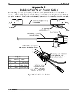
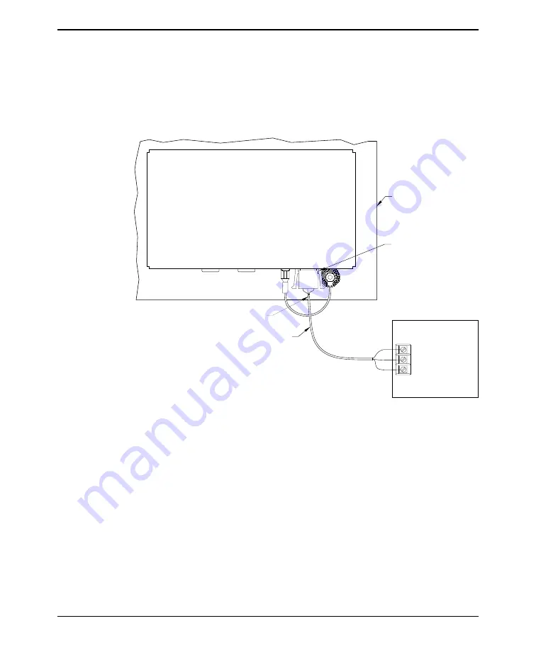
1. Plug the orange connector on Maple Systems Cable 7431-0050A into the
power connector on the OIT.
2. Route the power cable to the OIT power supply.
3. The power cable should not be any longer than necessary. If needed:
a) cut the power supply cable to the appropriate length.
b) strip the cable shield back on the power cable.
c) strip the insulation from the red and black wires.
4. Install the wires into the power supply as follows:
RED
+ output
BLACK
– output
SHIELD
case ground
INSTALLATION MANUAL
11
1010-0081A, REV 04
Shielded Power Cable
Power Connector
Maple P/N 7431-0050A
OIT
Cover
Control Panel
Blk
Red
Shield
Wire
Refer to Appendix B for
complete instructions on building
your own power cable.
POWER SUPPLY
Output
Case GND
-
+
ote:
OIT
on shield wire
Ferrite shield beads
Figure 7 OIT3200/3250 Power Supply Connection


