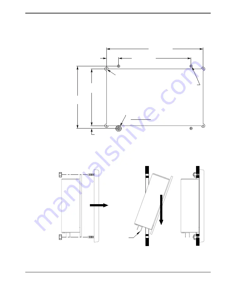
The diagram below shows the dimensions of the panel cutout required for proper
panel installation. The panel cutout should be cleaned and deburred before the OIT
is installed. Also the area around the lower right hand mounting hole (as viewed
from the rear) should be free of paint or anodizing to provide the OIT with a good
earth ground connection.
2.3. Mount OIT to Panel
INSTALLATION MANUAL
9
1010-0081A, REV 04
This area to be free of paint
5.15" +/-0.01
130.8mm +/-0.3
Corner drill permissable
4.70" +/-0.03
6.00" +/-0.01
152.4mm +/-0.3
8.00" +/-0.03
1.00" ref.
25.4mm
0.23" ref.
on REAR SIDE
4 places, up to 9/32 dia.
5.5mm +/-0.3
4 mounting holes
(7.1mm); otherwise,
R0.06" max (1.5mm)
5.8mm
119.4mm +/-0.8
203.2mm +/-0.8
on square corners
7/32(0.218)" +/-0.01 dia.,
Figure 4 OIT3200/3250 Panel Cutout Dimensions-Front View
5A
Remove Bezel
Initial Placement
5B
Complete Placement
5C
Add Bezel and Nuts
CAUTION:
Do not damage
connectors
Figure 5 OIT3200/3250 Panel Mounting


