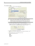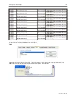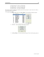
then it is because those windows have already been created. The Window Setting dialog box
appears.
4.
Modify the window parameters, then press
OK
. The Open Window dialog box reappears.
5.
If you wish to open the window you just created, click on the window and click
Open
.
Otherwise, click
Exit
to return to the main screen of EasyBuilder.
Win dow Set tings
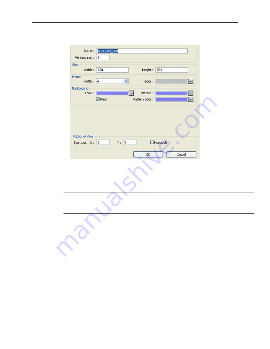
Let’s look more closely at the parameters you can change when creating a new window.
When a window is initially created, the window settings can be edited to make
changes; however, once a window has been created, the window number can not be
changed. To change the window settings, highlight the desired window and click on the
Setting...
button.
Assigning a Window Name
The Name is a description box used to help you identify what the window is used for without having to actually
open the window and look at the contents. Up to 50 characters can be entered into this field with space characters
allowed.
Assigning the Window Number
Although 1999 windows are available on the Silver Plus Series, two are specifically reserved for the Common
Window and the Fast Selection window and several are reserved for internal use. Therefore, you can assign
#10-1999 to any window you create. When you initially create a window, EasyBuilder will automatically assign the
lowest available number to the window. However, you can assign any number within the allowed range. In this
manner, you can group windows together that may share some common traits.
Assigning a Position
This is the starting position that the window goes to when it is initially called onto the OIT screen. The starting
position is labeled Start Pos: in the Window Setting Dialog box. The X and Y positions refer to the pixel location of
the OIT display at which the upper left hand corner of the window is to be displayed.
The default setting is X=0 and Y=0 which is the upper left hand corner of the OIT display. The X-axis refers to the
horizontal location and the Y-axis refers to the vertical location. The HMI5056 has a 320 x 240 pixel display, so
the ranges are X=0-319 and Y=0-239. The HMI5070 has a 480 x 234 pixel display, so the ranges are X=0-479 and
Y=0-233. The HMI5080/5104 has a 640 x 480 pixel display, so the ranges are X=0-639 and Y=0-479. The
1010-1007, Rev 05
108
Sil ver Plus Se ries In stal la tion & Op er a tion Man ual
Summary of Contents for Silver Plus Series
Page 20: ...1010 1007 Rev 05 16 Silver Plus Series Installation Operation Manual ...
Page 31: ...COM Ports for the HMI5056 5070 1010 1007 Rev 05 Connect the OIT to the PLC or Controller 27 ...
Page 38: ...1010 1007 Rev 05 34 Silver Plus Series Installation Operation Manual ...
Page 49: ...7 Click the Shape tab 1010 1007 Rev 05 Creating Your First Project 45 ...
Page 62: ...1010 1007 Rev 05 58 Silver Plus Series Installation Operation Manual ...
Page 75: ...3 Click OK The System Parameter Settings dialog appears 1010 1007 Rev 05 Using EZware 5000 71 ...
Page 132: ...1010 1007 Rev 05 128 Silver Plus Series Installation Operation Manual ...
Page 156: ...1010 1007 Rev 05 152 Silver Plus Series Installation Operation Manual ...
Page 210: ...1010 1007 Rev 05 206 Silver Plus Series Installation Operation Manual ...
Page 216: ...1010 1007 Rev 05 212 Silver Plus Series Installation Operation Manual ...
Page 246: ...1010 1007 Rev 05 242 Silver Plus Series Installation Operation Manual ...

