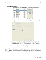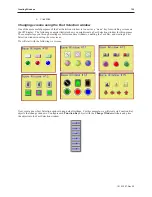
2.
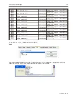
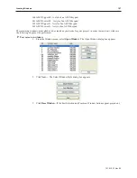
Click
New...
. The PLC Control dialog appears.
3.
Select the
Device type
and
Device Address
for the actual PLC address you wish to monitor.
The OIT will write the number of the newly-displayed window to the next consecutive
address after the address specified in this step.
4.
Select the
format
from the drop down menu (16-bit or 32-bit unsigned, signed or BCD).
5.
Click
OK
to return to the PLC Control Object dialog box.
6.
You will see a new entry that lists the PLC address that is monitored by the OIT.
The PLC must only enter window numbers that represent full size windows when using the PLC Control Object
function. The OIT automatically closes any open windows before the window called by the PLC Control Object is
displayed.
The Direct and Indirect Window Objects
If you want the PLC to call up a popup window that is to be overlaid on top of other windows already open, then
there are two methods used to do this:
• Direct Window Object
• Indirect Window Object
Unlike the PLC Control Object, the Direct and Indirect Window Objects are only active
for the windows into which they are placed.
The Direct Window Object is used to display a popup window using a PLC coil. The OIT continuously reads the
value of the PLC coil to determine if it is set to 1. If so, then the predefined popup window is displayed.
The Indirect Window Object is used to display a popup window using a PLC data register. Similar to the PLC
Control Object, the OIT continuously monitors the selected PLC data register. It will display any popup window
that corresponds to the number placed into the PLC data register by the PLC.
The PLC must reference a window that is less than full size when using the Direct Window and Indirect Window
objects.
1010-1007, Rev 05
Cre ating Win dows
115
Summary of Contents for Silver Plus Series
Page 20: ...1010 1007 Rev 05 16 Silver Plus Series Installation Operation Manual ...
Page 31: ...COM Ports for the HMI5056 5070 1010 1007 Rev 05 Connect the OIT to the PLC or Controller 27 ...
Page 38: ...1010 1007 Rev 05 34 Silver Plus Series Installation Operation Manual ...
Page 49: ...7 Click the Shape tab 1010 1007 Rev 05 Creating Your First Project 45 ...
Page 62: ...1010 1007 Rev 05 58 Silver Plus Series Installation Operation Manual ...
Page 75: ...3 Click OK The System Parameter Settings dialog appears 1010 1007 Rev 05 Using EZware 5000 71 ...
Page 132: ...1010 1007 Rev 05 128 Silver Plus Series Installation Operation Manual ...
Page 156: ...1010 1007 Rev 05 152 Silver Plus Series Installation Operation Manual ...
Page 210: ...1010 1007 Rev 05 206 Silver Plus Series Installation Operation Manual ...
Page 216: ...1010 1007 Rev 05 212 Silver Plus Series Installation Operation Manual ...
Page 246: ...1010 1007 Rev 05 242 Silver Plus Series Installation Operation Manual ...

