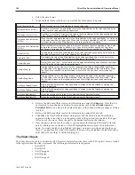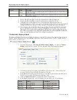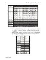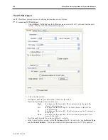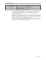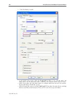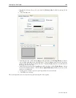
32-bit BCD
Left of Dec. Pt.
1 to 11
Digits to display to the left of the Decimal Point
Right of Dec. Pt.
0 to 11
Digits to display to the right of the Decimal Point
16-bit Hex
Left of Dec. Pt.
N/A
Displays 4 hex digits to the left of the Decimal Point
Right of Dec. Pt.
N/A
No digits are displayed to the right of the Decimal Point
32-bit Hex
Left of Dec. Pt.
N/A
Displays 8 hex digits to the left of the Decimal Point
Right of Dec. Pt.
N/A
No digits are displayed to the right of the Decimal Point
16-bit Binary
Left of Dec. Pt.
N/A
Displays 16 binary digits to the left of the Decimal Point
Right of Dec. Pt.
N/A
No digits are displayed to the right of the Decimal Point
32-bit Binary
Left of Dec. Pt.
N/A
Displays 32 binary digits to the left of the Decimal Point
Right of Dec. Pt.
N/A
No digits are displayed to the right of the Decimal Point
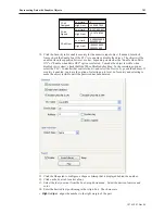
16-bit Unsigned
Left of Dec. Pt.
1 to 11
Digits to display to the right of the Decimal Point
Right of Dec. Pt.
0 to 11
Digits to display to the left of the Decimal Point
16-bit Signed
Left of Dec. Pt
1 to 11
Digits to display to the right of the Decimal Point
Right of Dec. Pt.
0-11
Digits to display to the left of the Decimal Point
32-bit Unsigned
Left of Dec. Pt
1 to 11
Digits to display to the right of the Decimal Point
Right of Dec. Pt.
0-11
Digits to display to the left of the Decimal Point
32-bit Signed
Left of Dec. Pt
1 to 11
Digits to display to the right of the Decimal Point
Right of Dec. Pt.
0-11
Digits to display to the left of the Decimal Point
32-bit Float
Left of Dec. Pt
1 to 11
Digits to display to the right of the Decimal Point
Right of Dec. Pt.
0-11
Digits to display to the left of the Decimal Point
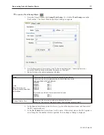
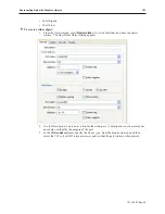
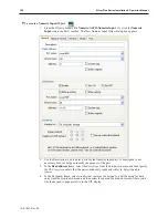
8. The Unsigned, Signed, and Float formats have the option of scaling the data. To display a
scaled value, check the
Do Conversion
box. In the
Engineering Low
field, enter the
lowest
value
that the OIT is to display. In the
Engineering High
field, enter the
highest value
that the
OIT is to display. The conversion will also use the Low and High limits specified in the
Limits section.
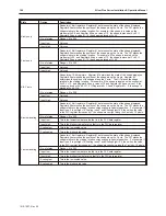
9. In the
Limits
section, first select if the Input Low and High values will be entered directly, or
read from a series of PLC registers. If read from a register, the Low Limit is read from the
specified register, and the High Limit is read from the next consecutive register. In either
case, the valid ranges are listed below.
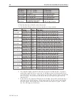
Format
Options
Range
16-bit BCD
Low Limit
0
High Limit
65,535
32-bit BCD
Low Limit
0
High Limit
4,294,967,295
16-bit Hex
Low Limit
0
High Limit
65,535
32-bit Hex
Low Limit
0
High Limit
4,294,967,295
16-bit Binary
Low Limit
0
High Limit
65,535
32-bit Binary
Low Limit
0
High Limit
4,294,967,295
16-bit
Unsigned
Low Limit
0
High Limit
65535
16-bit
Signed
Low Limit
-32,768
High Limit
32,768
1010-1007, Rev 05
190
Sil ver Plus Se ries In stal la tion & Op er a tion Man ual
Summary of Contents for Silver Plus Series
Page 20: ...1010 1007 Rev 05 16 Silver Plus Series Installation Operation Manual ...
Page 31: ...COM Ports for the HMI5056 5070 1010 1007 Rev 05 Connect the OIT to the PLC or Controller 27 ...
Page 38: ...1010 1007 Rev 05 34 Silver Plus Series Installation Operation Manual ...
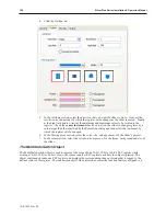
Page 49: ...7 Click the Shape tab 1010 1007 Rev 05 Creating Your First Project 45 ...
Page 62: ...1010 1007 Rev 05 58 Silver Plus Series Installation Operation Manual ...
Page 75: ...3 Click OK The System Parameter Settings dialog appears 1010 1007 Rev 05 Using EZware 5000 71 ...
Page 132: ...1010 1007 Rev 05 128 Silver Plus Series Installation Operation Manual ...
Page 156: ...1010 1007 Rev 05 152 Silver Plus Series Installation Operation Manual ...
Page 210: ...1010 1007 Rev 05 206 Silver Plus Series Installation Operation Manual ...
Page 216: ...1010 1007 Rev 05 212 Silver Plus Series Installation Operation Manual ...
Page 246: ...1010 1007 Rev 05 242 Silver Plus Series Installation Operation Manual ...

