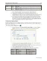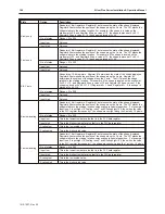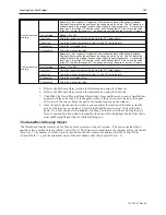
X axis w/reverse
scaling
Reads two 16-bit registers. Register #1 determines the state of the shape displayed.
Register #2 determines the position of the shape along the X axis. The OIT places the
shape relative to the starting location using scaling to calculate position. For example, if
Input low=0, Input high=10, Scaling low=0, and Scaling high=100, then when the value
in the PLC register increases by 1, the shape moves
left
along the X axis by 10 pixels.
No. of states:
Range = 0 to 255
Input low:
This is the lowest raw data value that is in the PLC data register
Input high:
This is the highest raw data value that is in the PLC data register
Scaling low:
This is the low scaled value.
Scaling high:
This is the high scaled value.
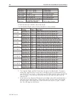
Y axis w/reverse
scaling
Reads two 16-bit registers. Register #1 determines the state of the shape displayed.
Register #2 determines the position of the shape along the Y axis. The OIT places the
shape relative to the starting location using scaling to calculate position. For example, if
Input low=0, Input high=10, Scaling low=0, and Scaling high=100, then when the value
in the PLC register increases by 1, the shape moves
up
along the Y axis by 10 pixels.
No. of states:
Range = 0 to 255
Input low:
This is the lowest raw data value that is in the PLC data register
Input high:
This is the highest raw data value that is in the PLC data register
Scaling low:
This is the low scaled value.
Scaling high:
This is the high scaled value.
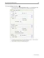
5.
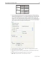
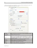
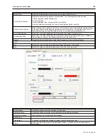
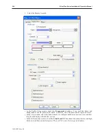
Refer to the Bit Lamp Object section for information on using the Shape tab.
6.
Refer to the Bit Lamp Object section for information on using the Label tab.
7.
Click
OK
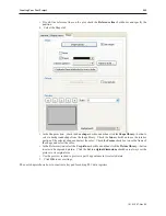
. The Create Moving Shape Object form closes and the main screen of EasyBuilder
appears with the cursor tied to a rectangular outline of the part you just created at the upper
left corner of the screen. Move the part to the desired location on the window.
8.
Once the part is placed onto the window, you can adjust the location of the label inside the
part by clicking once on the label. This will highlight the entire object. Click on the label
again. Now only the label is highlighted, allowing you to move it without moving the part.
Note: if you double-click (click twice rapidly) then you will not highlight the label but rather
enter the Moving Shape Object’s Attribute dialog box.
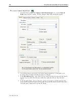
The Data Block Display Object
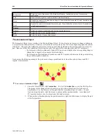
The Data Block Displays creates a Line Graph of data stored in a series of registers. The plot is created when a
specific value is written to the specified
Control Word
. The data must be loaded into the registers before the Control
Word is set. The number of values to plot is specified in the next consecutive address after the Control Word
(Control Word + 1), and the actual data starts at the next address after that (Control Word + 2).
1010-1007, Rev 05
Cre ating Your First Project
197
Summary of Contents for Silver Plus Series
Page 20: ...1010 1007 Rev 05 16 Silver Plus Series Installation Operation Manual ...
Page 31: ...COM Ports for the HMI5056 5070 1010 1007 Rev 05 Connect the OIT to the PLC or Controller 27 ...
Page 38: ...1010 1007 Rev 05 34 Silver Plus Series Installation Operation Manual ...
Page 49: ...7 Click the Shape tab 1010 1007 Rev 05 Creating Your First Project 45 ...
Page 62: ...1010 1007 Rev 05 58 Silver Plus Series Installation Operation Manual ...
Page 75: ...3 Click OK The System Parameter Settings dialog appears 1010 1007 Rev 05 Using EZware 5000 71 ...
Page 132: ...1010 1007 Rev 05 128 Silver Plus Series Installation Operation Manual ...
Page 156: ...1010 1007 Rev 05 152 Silver Plus Series Installation Operation Manual ...
Page 210: ...1010 1007 Rev 05 206 Silver Plus Series Installation Operation Manual ...
Page 216: ...1010 1007 Rev 05 212 Silver Plus Series Installation Operation Manual ...
Page 246: ...1010 1007 Rev 05 242 Silver Plus Series Installation Operation Manual ...

