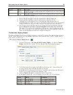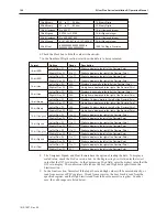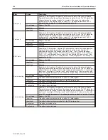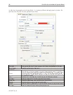
An offset may be optionally used at (Control Word + 2), to indicate a different starting location for the data. The
specified value is the offset from the specified Control Word.
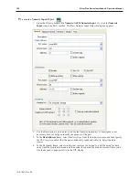
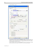
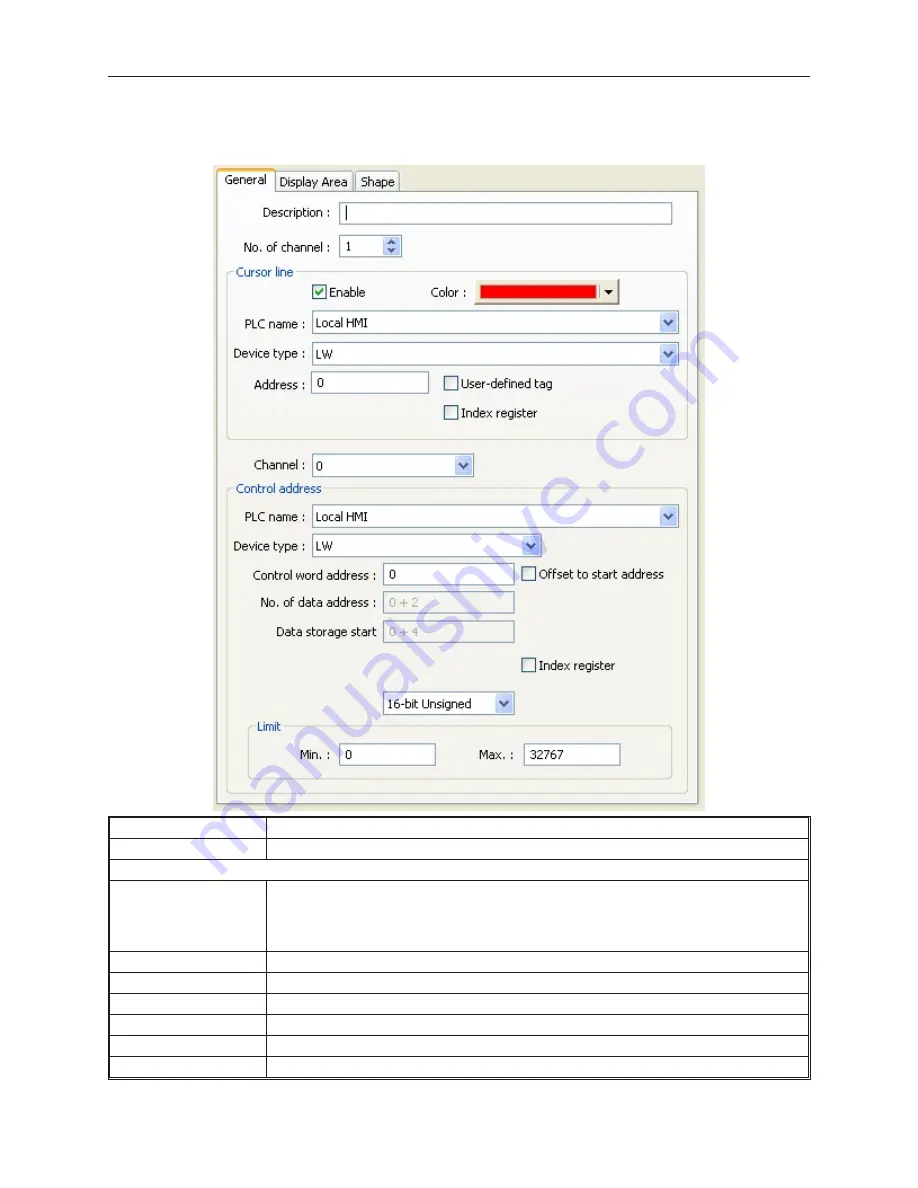
Description
Enter a
name
for the object. This isn’t necessary, but will help in later identification of the object.
No. of Channel
Specify the number of sets of data to plot.
Cursor Line
Enable
When enabled, a vertical line will appear on the plot to select a particular location. As the line is
moved, the value(s) at that location is/are loaded into the specified register. The specified register
contains the index of the selected data point (0,1, 2, 3, etc). The next register contains the data
value for that point. If multiple plots are displayed, the values from those plots are loaded into the
next consecutive registers.
Color
Specify the color of the Cursor Line. Available only when the Enable box is checked.
PLC Name
Select the configured PLC to in which to store the Cursor Line data
Device Type
Specify the register/storage type in which to store the Cursor Line data.
Address
Specify the location in which to store the Cursor Line data.
Channel
Select the channel to configure below. Each of the following fields can be unique for each channel.
PLC Name
Select the configured PLC from which to retrieve the data to plot.
1010-1007, Rev 05
198
Sil ver Plus Se ries In stal la tion & Op er a tion Man ual
Summary of Contents for Silver Plus Series
Page 20: ...1010 1007 Rev 05 16 Silver Plus Series Installation Operation Manual ...
Page 31: ...COM Ports for the HMI5056 5070 1010 1007 Rev 05 Connect the OIT to the PLC or Controller 27 ...
Page 38: ...1010 1007 Rev 05 34 Silver Plus Series Installation Operation Manual ...
Page 49: ...7 Click the Shape tab 1010 1007 Rev 05 Creating Your First Project 45 ...
Page 62: ...1010 1007 Rev 05 58 Silver Plus Series Installation Operation Manual ...
Page 75: ...3 Click OK The System Parameter Settings dialog appears 1010 1007 Rev 05 Using EZware 5000 71 ...
Page 132: ...1010 1007 Rev 05 128 Silver Plus Series Installation Operation Manual ...
Page 156: ...1010 1007 Rev 05 152 Silver Plus Series Installation Operation Manual ...
Page 210: ...1010 1007 Rev 05 206 Silver Plus Series Installation Operation Manual ...
Page 216: ...1010 1007 Rev 05 212 Silver Plus Series Installation Operation Manual ...
Page 246: ...1010 1007 Rev 05 242 Silver Plus Series Installation Operation Manual ...


