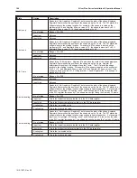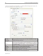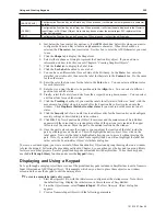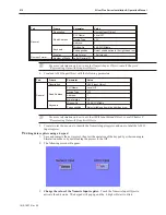
Device Type
Select the register/storage type from which to retrieve the data to plot.
Control Word Address
Specify the location of the graph’s control address. The following values may be used:
1: Draws the graph, leaves existing data.
2: Clears the graph.
3: Clears the graph, then redraws with the current data.
After the operation is complete, the Control Word Address will be reset to 0.
Offset to Start Address
When checked, the location (Control Word + 2) will contain a value indicating the starting address
of the data, offset from the address specified for the Control Word. For example, if the Control
Word address is set to 0, and the offset is set to 10, the data will start at address 10.
No. of Data Address
Read Only
. Indicates the address that will contain the number of points to plot.
Data Storage Start
Read Only
. Indicates the address that will contain the first of the data points to plot. If
Offset to
Start Address
is checked, this indicates the location of the offset value.
Format
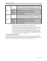
Specify the format of the data to graph. Each channel may have a different format.
Limit
Min
Specify the value at which the plotted line will be at the bottom of the graph.
Max
Specify the value at which the plotted line will be at the top of the graph.
Data Samples
Specify the number of points to display on each page.
Sample to Scroll
Specify the number of points to move each time a Scroll Button is pressed.
Enable Scroll Switch
When checked, the Scroll Buttons are displayed.
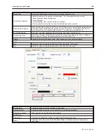
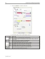
Profile Color
Transparent
If checked, the Data Block Display is created without a background color.
Frame
Select the color of the border of the Data Block Display. Available only when
Transparent
is
unchecked.
1010-1007, Rev 05
Cre ating Your First Project
199
Summary of Contents for Silver Plus Series
Page 20: ...1010 1007 Rev 05 16 Silver Plus Series Installation Operation Manual ...
Page 31: ...COM Ports for the HMI5056 5070 1010 1007 Rev 05 Connect the OIT to the PLC or Controller 27 ...
Page 38: ...1010 1007 Rev 05 34 Silver Plus Series Installation Operation Manual ...
Page 49: ...7 Click the Shape tab 1010 1007 Rev 05 Creating Your First Project 45 ...
Page 62: ...1010 1007 Rev 05 58 Silver Plus Series Installation Operation Manual ...
Page 75: ...3 Click OK The System Parameter Settings dialog appears 1010 1007 Rev 05 Using EZware 5000 71 ...
Page 132: ...1010 1007 Rev 05 128 Silver Plus Series Installation Operation Manual ...
Page 156: ...1010 1007 Rev 05 152 Silver Plus Series Installation Operation Manual ...
Page 210: ...1010 1007 Rev 05 206 Silver Plus Series Installation Operation Manual ...
Page 216: ...1010 1007 Rev 05 212 Silver Plus Series Installation Operation Manual ...
Page 246: ...1010 1007 Rev 05 242 Silver Plus Series Installation Operation Manual ...

