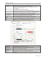
Background
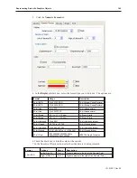
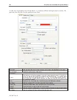
Select the color of the interior of the Data Block Display. Available only when
Transparent
is
unchecked.
Grid
When checked, a grid is created within the Data Block Display.
Horiz.
Specify the number of Vertical lines in the grid. These define the horizontal (X) axis. Available only
when
Enable
is checked.
Verti.
Specify the number of Horizontal lines in the grid. These define the vertical (Y) axis. Available only
when
Enable
is checked.
Channel
Channel
Select the channel whose properties are to be configured below.
Color
Select the color for the specified channel.
Width
Select the width of the specified channel.
The An i ma tion Ob ject
The Animation Object is very similar to the Moving Shape Object. It also allows you to create a shape or bitmap on
a screen that can change the way it looks as well as where it is located on the OIT screen depending upon the control
of the PLC. However, the Animation Object moves along a predefined path that is determined when you create the
part. Because of this, the Animation Object requires only two registers for changing state and X/Y movement:
• the Animation object continuously reads a PLC register and displays the corresponding shape or
bitmap that is tagged to the number of states defined.
• the Animation object continuously reads a second PLC register to determine which position along
the predefined path it should be.
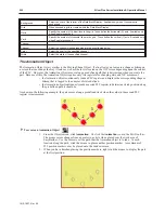
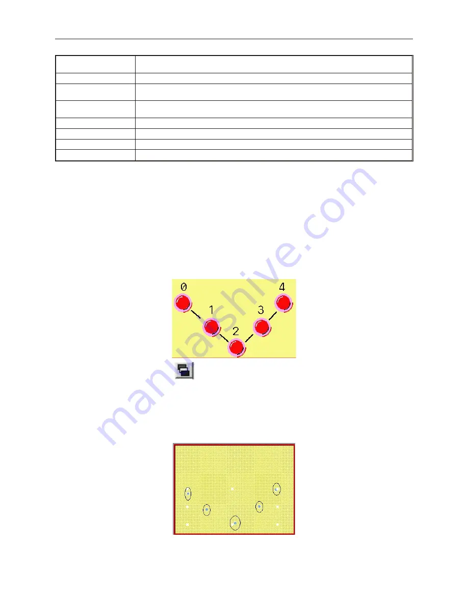
As shown in the following example, the part moves along a predefined track when the value in the second PLC
register is incremented:
4
To create an Animation Object
1.
From the Objects
menu, click
Animation
. Or click the
Animation
icon in the Part2 toolbar.
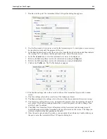
The mouse cursor changes from a pointer to a circle when placed over the work area of
EasyBuilder. Use the cursor to set the path that the Animation object is to take. At each
location along the path, click the mouse to place another position marker. A maximum of
255 position markers may be placed onto the window screen.
2.
When you have finished placing the position markers, right click the mouse to display the part
at the first position.
1010-1007, Rev 05
200
Sil ver Plus Se ries In stal la tion & Op er a tion Man ual
Summary of Contents for Silver Plus Series
Page 20: ...1010 1007 Rev 05 16 Silver Plus Series Installation Operation Manual ...
Page 31: ...COM Ports for the HMI5056 5070 1010 1007 Rev 05 Connect the OIT to the PLC or Controller 27 ...
Page 38: ...1010 1007 Rev 05 34 Silver Plus Series Installation Operation Manual ...
Page 49: ...7 Click the Shape tab 1010 1007 Rev 05 Creating Your First Project 45 ...
Page 62: ...1010 1007 Rev 05 58 Silver Plus Series Installation Operation Manual ...
Page 75: ...3 Click OK The System Parameter Settings dialog appears 1010 1007 Rev 05 Using EZware 5000 71 ...
Page 132: ...1010 1007 Rev 05 128 Silver Plus Series Installation Operation Manual ...
Page 156: ...1010 1007 Rev 05 152 Silver Plus Series Installation Operation Manual ...
Page 210: ...1010 1007 Rev 05 206 Silver Plus Series Installation Operation Manual ...
Page 216: ...1010 1007 Rev 05 212 Silver Plus Series Installation Operation Manual ...
Page 246: ...1010 1007 Rev 05 242 Silver Plus Series Installation Operation Manual ...

