3.
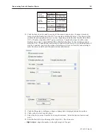
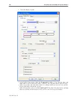
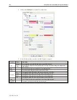
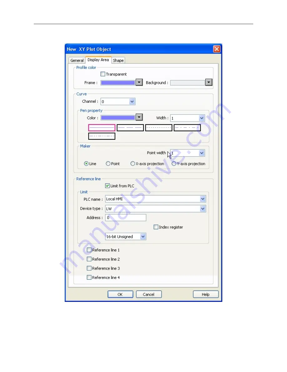
Select the Display Area tab:.
• In the Profile Color section, check the
Transparent
checkbox if you wish the frame and
background of the XY plot to be invisible. Otherwise, select the
frame
and
background
colors.
• In the Curve section, select the
channel number
to configure and then set
pen properties
and how
the plot will display in the Maker section.
• In the Reference line section, check the
Limit from PLC
checkbox if checked, the low and high
limits are read from controller register. Then set
PLC name
,
Device type
and
Address
.
1010-1007, Rev 05
204
Sil ver Plus Se ries In stal la tion & Op er a tion Man ual
Summary of Contents for Silver Plus Series
Page 20: ...1010 1007 Rev 05 16 Silver Plus Series Installation Operation Manual ...
Page 31: ...COM Ports for the HMI5056 5070 1010 1007 Rev 05 Connect the OIT to the PLC or Controller 27 ...
Page 38: ...1010 1007 Rev 05 34 Silver Plus Series Installation Operation Manual ...
Page 49: ...7 Click the Shape tab 1010 1007 Rev 05 Creating Your First Project 45 ...
Page 62: ...1010 1007 Rev 05 58 Silver Plus Series Installation Operation Manual ...
Page 75: ...3 Click OK The System Parameter Settings dialog appears 1010 1007 Rev 05 Using EZware 5000 71 ...
Page 132: ...1010 1007 Rev 05 128 Silver Plus Series Installation Operation Manual ...
Page 156: ...1010 1007 Rev 05 152 Silver Plus Series Installation Operation Manual ...
Page 210: ...1010 1007 Rev 05 206 Silver Plus Series Installation Operation Manual ...
Page 216: ...1010 1007 Rev 05 212 Silver Plus Series Installation Operation Manual ...
Page 246: ...1010 1007 Rev 05 242 Silver Plus Series Installation Operation Manual ...

