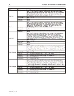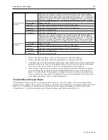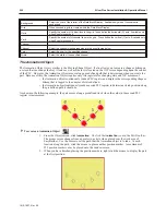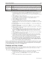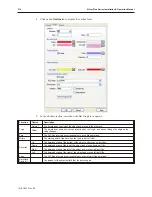
[BACK SPACE]
Configures the Function Key as a Delete key. When pressed, it will delete the last alphanumeric character
entered.
[CLEAR]
Configures the Function Key as a Clear key. When pressed, it will clear the data displayed in the Numeric
Input Object or ASCII Input Object. Note: this key does not clear the actual target PLC register until the
Enter key is pressed.
[ESC]
Configures the Function Key as an Escape key. When pressed, it will exit the editing mode.
4.
Just below the four control key options, is the
ASCII
checkbox. Select this when you want to
configure the Function Key to enter an alphanumeric character. When this checkbox is
selected, the
Character:
box is activated. Use this box to enter the ASCII character you want
to use.
5.
Click the
Shape
tab to display the Shape form.
6.
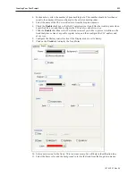
Select either a shape or bitmap to represent the Function Key object. If you need more
information on how to do this, consult Chapter 6 “Creating Graphics Objects”.
7.
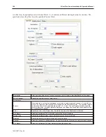
Click the
Label
tab to display the Label form.
8.
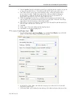
Click the
Use Label
checkbox to use a label.
9.
You can have a different label for each state of the Bit Lamp. In the
State:
box, enter the
state that you wish to edit, then enter the label for that state in the
Content:
box. Do the same
for the other state.
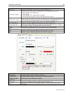
10. Enter the color that you want for the label in the
Color:
box. You can select a different color
for each label state.
11. Enter how you want the label to be positioned in the
Align:
box. You can select a different
position for each label state.
12. Finally, select the font style and size from their respective drop down menus.. You can select
a different font for each label state.
13. Click the
Tracking
checkbox if you want the labels for all states to follow or ‘track’ with the
movement of one label when it is moved after the Function Key object is placed onto the
window. Click
Duplicate this label to other states
if you want to use the same text on all
states.
14. Click the
Security
tab if you would like to enable security for the function key and configure
security settings as described in previous sections.
15. Click
OK
. The New Function Key Object form closes and the main screen of EasyBuilder
appears with the cursor tied to a rectangular outline of the part you just created at the upper
left corner of the screen. Move the part to the desired location on the window.
16. Once the part is placed onto the window, you can adjust the location of the label inside the
part by clicking once on the label. This will highlight the entire object. Now click on the
label again. Now only the label is highlighted, allowing you to move it without moving the
part. Note: if you double-click (click twice rapidly) then you will not highlight the label but
rather enter the Function Key Object’s Attribute dialog box.
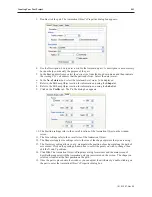
To create a custom keypad, you create several of these Function Key Objects and group them together on a window
to form the keypad. Following the procedure outlined in Chapter 6, you can then save the keypad to a group library
for later use in other projects. Several predefined keypads are included with EasyBuilder. To use these keypads,
use the
Call Group Library
function and access the
keypad
library.
Dis playing and Using a Key pad
Let’s go through a sample project that uses one of the predefined keypads included in EasyBuilder to edit a Numeric
Input Object and an ASCII Input Object. This example will show you how to place these objects on a window
screen, and then use the keypad to edit the data registers.
4
To create a sample keypad entry screen
1.
Start a new project file, with the initial screen configured as the startup screen. Note: this is
the default setting. Display the initial screen in the work area of EasyBuilder.
2.
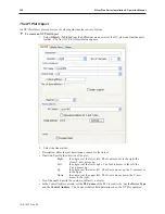
From the Objects menu, select
Numeric Input
. The New Numeric Object dialog box
appears.
3.
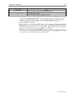
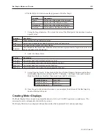
Create a Numeric Input Object with the following parameters:
1010-1007, Rev 05
Using and Cre ating Key pads
209
Summary of Contents for Silver Plus Series
Page 20: ...1010 1007 Rev 05 16 Silver Plus Series Installation Operation Manual ...
Page 31: ...COM Ports for the HMI5056 5070 1010 1007 Rev 05 Connect the OIT to the PLC or Controller 27 ...
Page 38: ...1010 1007 Rev 05 34 Silver Plus Series Installation Operation Manual ...
Page 49: ...7 Click the Shape tab 1010 1007 Rev 05 Creating Your First Project 45 ...
Page 62: ...1010 1007 Rev 05 58 Silver Plus Series Installation Operation Manual ...
Page 75: ...3 Click OK The System Parameter Settings dialog appears 1010 1007 Rev 05 Using EZware 5000 71 ...
Page 132: ...1010 1007 Rev 05 128 Silver Plus Series Installation Operation Manual ...
Page 156: ...1010 1007 Rev 05 152 Silver Plus Series Installation Operation Manual ...
Page 210: ...1010 1007 Rev 05 206 Silver Plus Series Installation Operation Manual ...
Page 216: ...1010 1007 Rev 05 212 Silver Plus Series Installation Operation Manual ...
Page 246: ...1010 1007 Rev 05 242 Silver Plus Series Installation Operation Manual ...


