4
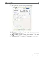
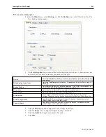
To create a backup part:
1. From the
Object
menu, select
Backup
, or click the
Backup
icon on the Object2 toolbar. The
New Backup dialog appears.
2.
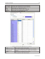
Use the
Description:
box to enter a title for the MultiState Switch part. A description is not
necessary but does help you identify the purpose of the part.
Source
Select which dataset to back up.
Data Log
is available only if a Data Sample has
been set up.
Data Sampling Object Index
Select the Data Sample set to back up. Available only when the Source is set to
Data Log
.
Backup Position
Select which USB device to back the data up to. Note: USB1 is the device that
was installed first; USB2 is the device that was installed last.
Range Start
Select whether to start with
Today’s
data or
Yesterday’s
data.
Range Within
Select the number of days’ worth of data to back up.
Attribute Mode
Touch Trigger
causes the backup to execute when the object is touched.
External Trigger
causes the backup to execute when the specified bit transitions.
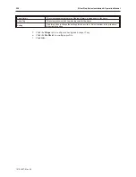
Attribute Trigger Mode
Specify how the bit must change to trigger the backup. Available only when
Attribute Mode is set to
External Trigger
.
Trigger Address
Specify the
bit
address with which to trigger the backup. Available only when
Attribute Mode is set to
External Trigger
.
3.
Click the
Security
tab and configure security settings, if needed.
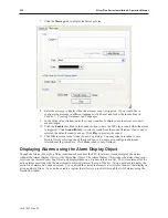
4. Click the
Shape
tab to configure background shape, if needed.
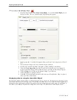
5.
Click the
Label
tab to apply a text label, if needed.
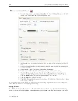
6.
Click
OK.
1010-1007, Rev 05
Cre ating Your First Project
241
Summary of Contents for Silver Plus Series
Page 20: ...1010 1007 Rev 05 16 Silver Plus Series Installation Operation Manual ...
Page 31: ...COM Ports for the HMI5056 5070 1010 1007 Rev 05 Connect the OIT to the PLC or Controller 27 ...
Page 38: ...1010 1007 Rev 05 34 Silver Plus Series Installation Operation Manual ...
Page 49: ...7 Click the Shape tab 1010 1007 Rev 05 Creating Your First Project 45 ...
Page 62: ...1010 1007 Rev 05 58 Silver Plus Series Installation Operation Manual ...
Page 75: ...3 Click OK The System Parameter Settings dialog appears 1010 1007 Rev 05 Using EZware 5000 71 ...
Page 132: ...1010 1007 Rev 05 128 Silver Plus Series Installation Operation Manual ...
Page 156: ...1010 1007 Rev 05 152 Silver Plus Series Installation Operation Manual ...
Page 210: ...1010 1007 Rev 05 206 Silver Plus Series Installation Operation Manual ...
Page 216: ...1010 1007 Rev 05 212 Silver Plus Series Installation Operation Manual ...
Page 246: ...1010 1007 Rev 05 242 Silver Plus Series Installation Operation Manual ...

