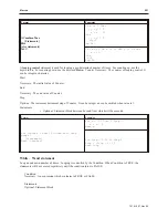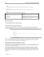
• bool: 1 bit
• arrays: the corresponding number of bytes for each element, plus another 2 bytes for the index
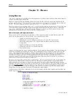
Macros use memory from the background task (defined as
Window 0
) area. There is a default memory size of
320K available for macros (only 220K is allotted if the ‘Fast Selection’ task bar is enabled) and the there are other
background task objects that also use memory in this area, such as:
• Trends
• Data Transfers
• Alarms
• Events
• PLC Controls
• Printer functions
If the application exceeds the 320k limit, both the simulator and the OIT will display a
System Severe Error message.
Variable Declarations
Each variable that will be used in the macro needs to be declared as a specific ‘type’ of register. The declarations are
listed as the first part of the macro. Any declarations contained within the macro function is considered ‘Local’ and
any variable outside the macro function is considered ‘Global’. Local variables are only seen within the function
they are declared in. Global variables retain their values and can be globally used by all functions. Below, are listed
the various data types that can be declared:
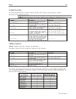
TypeDescription
Float
Single-Precision Floating point variable (32-bit signed,
IEEE-754 format)
Int
Integer variable (32-bit signed)
Short
Short integer variable (16-bit signed)
Char
Character variable (8-bit unsigned)
Bool
Boolean variable (1-bit)
Variables inside macros are initialized to all ‘1’s as a default (i.e. 0xFFFF), so don’t
assume they are zero values when you enter the macro. It is good programming
practice to initialize variables during declaration, or use assignment statements before
they are used.
Variable Initialization
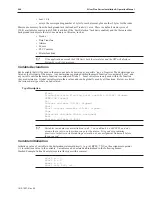
Initialize a value of variable in the declaration statement directly. (e.g: int RPM = 75) Use the assignment operator
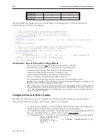
(=) to initialize a value to the variable. Variables can be declared and initialized in the following manor:
Stacked Example: Inline Example (separate like-types with a comma):
short a = 0
short b = 0
short c = 0
short a=0, b=0, c=0
1010-1007, Rev 05
246
Sil ver Plus Se ries In stal la tion & Op er a tion Man ual
Summary of Contents for Silver Plus Series
Page 20: ...1010 1007 Rev 05 16 Silver Plus Series Installation Operation Manual ...
Page 31: ...COM Ports for the HMI5056 5070 1010 1007 Rev 05 Connect the OIT to the PLC or Controller 27 ...
Page 38: ...1010 1007 Rev 05 34 Silver Plus Series Installation Operation Manual ...
Page 49: ...7 Click the Shape tab 1010 1007 Rev 05 Creating Your First Project 45 ...
Page 62: ...1010 1007 Rev 05 58 Silver Plus Series Installation Operation Manual ...
Page 75: ...3 Click OK The System Parameter Settings dialog appears 1010 1007 Rev 05 Using EZware 5000 71 ...
Page 132: ...1010 1007 Rev 05 128 Silver Plus Series Installation Operation Manual ...
Page 156: ...1010 1007 Rev 05 152 Silver Plus Series Installation Operation Manual ...
Page 210: ...1010 1007 Rev 05 206 Silver Plus Series Installation Operation Manual ...
Page 216: ...1010 1007 Rev 05 212 Silver Plus Series Installation Operation Manual ...
Page 246: ...1010 1007 Rev 05 242 Silver Plus Series Installation Operation Manual ...

