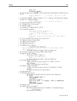
SetData(Section,
“Local HMI”
, LW_BIN,
2
,
1
)
for
Address =
0
to
29999
// increment the address
SetData(Address,
“Local HMI”
, LW_BIN,
9000
,
1
)
// write a
0
to
the current address
SetData(Initial,
“Local HMI”
, RWI_BIN,
0
,
1
)
next
address
// do the second half
Section =
2
SetData(Section,
“Local HMI”
, LW_BIN,
2
,
1
)
// adjust actual address by using LW9000
for
Address =
0
to
29999
// increment address
SetData(Address,
“Local HMI”
, LW_BIN,
9000
,
1
)
// write a
0
to
the current address
SetData(Initial,
“Local HMI”
, RWI_BIN,
30000
,
1
)
next
address
// turn off macro trigger, LB2
SetData(Initial,
“Local HMI”
, LB_BIN,
2
,
1
)
end
macro_command
Statements, Conditions & Expressions
An
expression
combines constants, variables, arrays, functions, and operators under certain rules. Expressions can
be logical or mathematical equations.
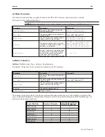
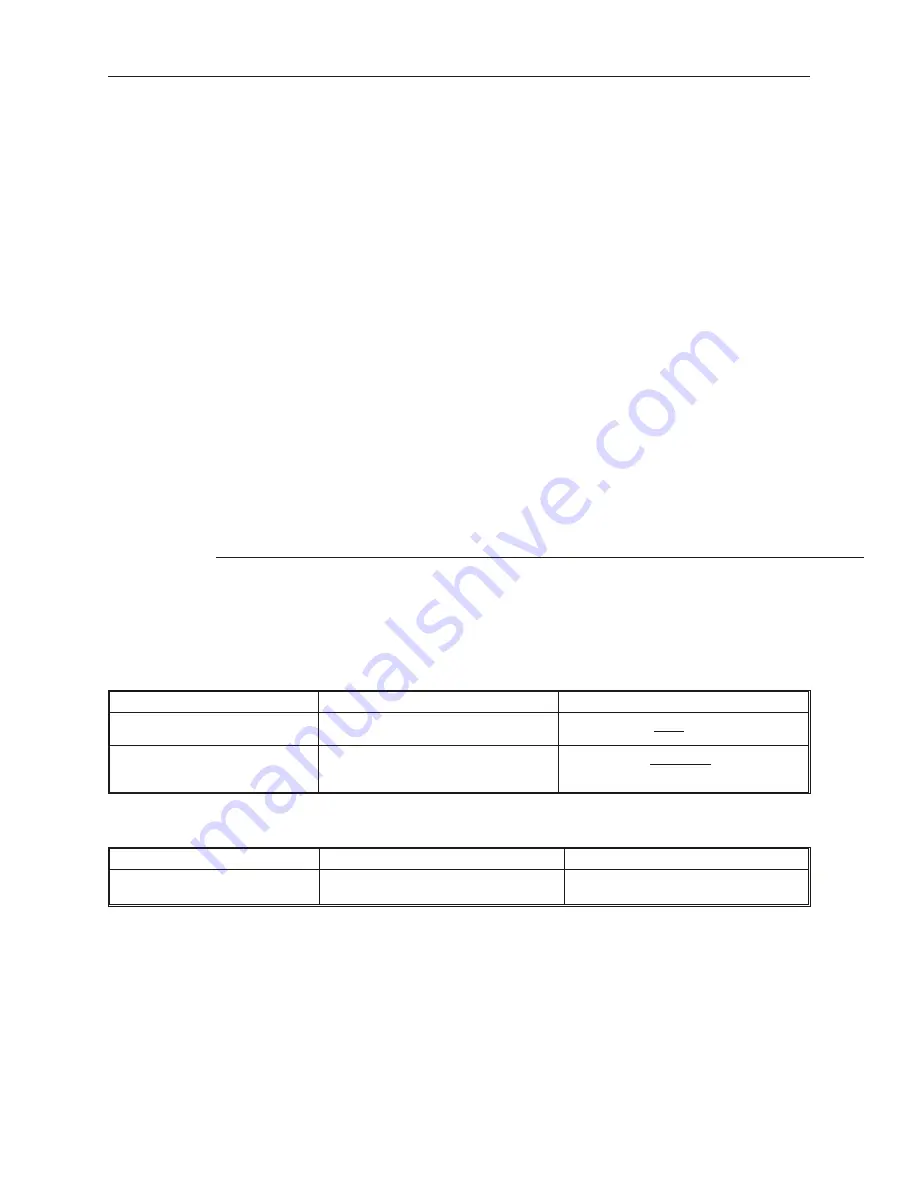
Below are listed some of the different styles of statements:
• A
declaration
(definition) statement is constructed like the following:
Format
Examples
Explanation
type
name
short
MyVar
This defines the name of the variable
register and its
type
type
name
[constant]
Short
MyVars[10]
This defines an array name and the
[constant] is the number of ‘
type
elements’
in the array
• An
assignment
statement will transfer (assign) an expression to a variable. The form is:
Format
Examples
Explanation
variable = expression
MyVar = 10
MyVar = x + y
This assigns the result of the expression to
a variable
•
A
logic
or
conditional
statement processes a logic expression and branches depending on the
result. This assigns the result of the expression to a variable. The ending statement
‘End If’
is
written as two words, not one word. Note that there is a difference between the conditional equality
noted by two equal signs ‘= =’ (read as: ‘is equal to’) and the assignment equality noted by only one
equal sign ‘=’.
1010-1007, Rev 05
250
Sil ver Plus Se ries In stal la tion & Op er a tion Man ual
Summary of Contents for Silver Plus Series
Page 20: ...1010 1007 Rev 05 16 Silver Plus Series Installation Operation Manual ...
Page 31: ...COM Ports for the HMI5056 5070 1010 1007 Rev 05 Connect the OIT to the PLC or Controller 27 ...
Page 38: ...1010 1007 Rev 05 34 Silver Plus Series Installation Operation Manual ...
Page 49: ...7 Click the Shape tab 1010 1007 Rev 05 Creating Your First Project 45 ...
Page 62: ...1010 1007 Rev 05 58 Silver Plus Series Installation Operation Manual ...
Page 75: ...3 Click OK The System Parameter Settings dialog appears 1010 1007 Rev 05 Using EZware 5000 71 ...
Page 132: ...1010 1007 Rev 05 128 Silver Plus Series Installation Operation Manual ...
Page 156: ...1010 1007 Rev 05 152 Silver Plus Series Installation Operation Manual ...
Page 210: ...1010 1007 Rev 05 206 Silver Plus Series Installation Operation Manual ...
Page 216: ...1010 1007 Rev 05 212 Silver Plus Series Installation Operation Manual ...
Page 246: ...1010 1007 Rev 05 242 Silver Plus Series Installation Operation Manual ...


