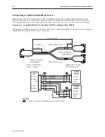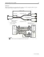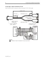
Connecting multiple PLC/controllers serially using daisy chaining
The RS485 4-wire and RS485 2-wire communications ports of the Silver Plus Series family supports multi-drop
connections. A daisy-chain connection is made from the OIT to the first PLC/controller, and then from the first
PLC/controller to the second and so on (see below). The network may need biasing resistors – refer to the
PLC/controller documentation for more information.
Refer to the Help Section of EasyBuilder-5000, under the How do I Section… for more
information.
Connecting one or more PLC/controllers via Ethernet
The Silver Plus Series OITs have a single RJ45 Ethernet connector, configured for 10BaseT and 100BaseT
operation. This port is for both communicating with a PC for configuration purposes, as well as for communicating
with supported Ethernet PLCs and protocols.
The connector is wired just like the RJ45 Ethernet connector on a PC. The Ethernet connection to a PLC/controller
will vary with each PLC/controller. Some will require a straight-through connection, while others require a
crossover connection. See Maple Systems' website for cable drawings of Ethernet cables.
4
To connect a single PLC/controller to an OIT
:
1.
Attach one end of the Ethernet cable to the RJ45 connector on the OIT
2.
Attach the other end to the RJ45 connector on the PLC/controller
A router or switch is required to connect multiple PLCs/controllers to a single OIT. In general, standard
straight-through type cables can be used when connecting to a PLC/controller through a router or switch. Some
routers and switches may be
auto-sensing
. In this case, either type of cable may be used.
1010-1007, Rev 05
Con nect the OIT to the PLC or Con trol ler
33
RS-485
Silver Plus Series OIT
PLC
PLC
PLC
PLC
Summary of Contents for Silver Plus Series
Page 20: ...1010 1007 Rev 05 16 Silver Plus Series Installation Operation Manual ...
Page 31: ...COM Ports for the HMI5056 5070 1010 1007 Rev 05 Connect the OIT to the PLC or Controller 27 ...
Page 38: ...1010 1007 Rev 05 34 Silver Plus Series Installation Operation Manual ...
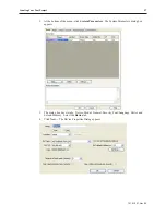
Page 49: ...7 Click the Shape tab 1010 1007 Rev 05 Creating Your First Project 45 ...
Page 62: ...1010 1007 Rev 05 58 Silver Plus Series Installation Operation Manual ...
Page 75: ...3 Click OK The System Parameter Settings dialog appears 1010 1007 Rev 05 Using EZware 5000 71 ...
Page 132: ...1010 1007 Rev 05 128 Silver Plus Series Installation Operation Manual ...
Page 156: ...1010 1007 Rev 05 152 Silver Plus Series Installation Operation Manual ...
Page 210: ...1010 1007 Rev 05 206 Silver Plus Series Installation Operation Manual ...
Page 216: ...1010 1007 Rev 05 212 Silver Plus Series Installation Operation Manual ...
Page 246: ...1010 1007 Rev 05 242 Silver Plus Series Installation Operation Manual ...


