4
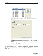
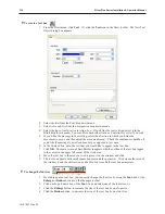
To create a scale
1.
From the Draw
menu, click
Scale
. Or click the
Scale
icon in the Draw toolbar
2.
Move the mouse cursor over to the work area of EasyBuilder onto the window that you are
currently editing. The mouse cursor has changed from an arrow to a crosshair cursor.
3.
Click to mark a corner of the scale. Move the mouse to where the opposite corner of the scale
should be. Click the mouse cursor again to mark the corner of the scale. The scale object is
formed and displayed on the window screen with small white square blocks around the
perimeter of the scale.
4.
From the Edit menu, select
Change Attribute
. The Scale Object’s Attribute dialog box
appears.
5.
In the Frame section of the Style tab, click the pull-down arrow of the
Color
box and select a
color. Click
OK
in the Color dialog box to go back to the Scale Object’s Attribute dialog
box.
6.
Click on the line thickness that you want to use.
7.
In the Scale section, select from one of the six
Styles
:
Up
Down
Full
¾ Size
Horizontal
Vertical
8.
Enter the number of divisions in the
Division:
box. For
Up, Down, Full,
and
¾
Size
enter
the
Meter Length
.
9.
Adjust the size and position of the scale in the Profile tab, if necessary.
10. Click
OK
. The Scale Object’s Attribute closes and the main screen of EasyBuilder reappears
with the Scale Object displayed. Scale lines are most often used when creating bar graphs,
scale meters, and trend graphs.
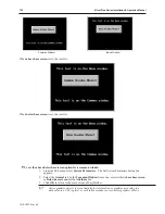
The Free Line Tool
The Free Line Tool allows you to draw lines in a free form fashion. .
4
To draw a free-form line
1.
From the Draw menu, select
Arbitrary line
or click on the
Free line
icon on the draw tool
bar. The Properties dialog appears.
2. Configure any
line properties
including color and line width.
3.
Move your cursor over EasyBuilder's design space. The cursor will turn into a crosshair.
When the crosshair is placed where you would like to begin your free line, left click your
mouse.
4.
Move your mouse along the path that you would like to draw your free line. This can include
any path - including a squiggly line, crossing over itself, etc. When you have completed your
line, right click your mouse button.
5. You may repeat steps 1-4 to continue drawing free lines, or you may click the
Select
icon on
the Draw toolbar, and then double click on your free lines to change any of the objects
attributes.
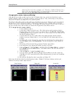
The Pie Tool
The pie tool allows you to draw a section of a circle -from 1
O
-360
O
.
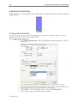
4
To use the pie tool
1.
Select
Pie
from the Draw menu or select the
Pie
icon from the draw tool bar. The Properties
dialog appears.
2.
Configure any properties for your shape, including line and fill.
1010-1007, Rev 05
132
Sil ver Plus Se ries In stal la tion & Op er a tion Man ual
Summary of Contents for Silver Plus Series
Page 20: ...1010 1007 Rev 05 16 Silver Plus Series Installation Operation Manual ...
Page 31: ...COM Ports for the HMI5056 5070 1010 1007 Rev 05 Connect the OIT to the PLC or Controller 27 ...
Page 38: ...1010 1007 Rev 05 34 Silver Plus Series Installation Operation Manual ...
Page 49: ...7 Click the Shape tab 1010 1007 Rev 05 Creating Your First Project 45 ...
Page 62: ...1010 1007 Rev 05 58 Silver Plus Series Installation Operation Manual ...
Page 75: ...3 Click OK The System Parameter Settings dialog appears 1010 1007 Rev 05 Using EZware 5000 71 ...
Page 132: ...1010 1007 Rev 05 128 Silver Plus Series Installation Operation Manual ...
Page 156: ...1010 1007 Rev 05 152 Silver Plus Series Installation Operation Manual ...
Page 210: ...1010 1007 Rev 05 206 Silver Plus Series Installation Operation Manual ...
Page 216: ...1010 1007 Rev 05 212 Silver Plus Series Installation Operation Manual ...
Page 246: ...1010 1007 Rev 05 242 Silver Plus Series Installation Operation Manual ...


