Power Sup ply Se lec tion
The power supply used to power the OIT should provide an output of +24 VDC 5% measured at the OIT power
terminal block. A 24VDC regulated power supply dedicated to the OIT is required. Use a power supply with a 1.1
Amp output rating for the HMI5056/5070 models and a 2.5 Amp output rating for all other models.
The power cable for the OIT should be 18AWG, 2-conductor wire with a shield drain wire and protective shield
(foil or braid). The shield drain wire must be connected to earth ground at both ends of the cable. Please refer to the
“Connect the OIT to Power” section for more information.
A power line filter installed at the AC input to the OIT power supply is highly recommended as a safeguard against
conducted RF noise, which is often present on factory power lines. The wires connecting the output of the power
line filter to the power supply should be kept as short as possible to minimize any additional noise pickup. The case
of the power line filter should be connected to a quiet earth ground. The power line filter should have a current
rating of at least 3 Amps with common mode and differential mode attenuation.
1010-1007, Rev 05
10
Sil ver Plus Se ries In stal la tion & Op er a tion Man ual
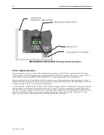
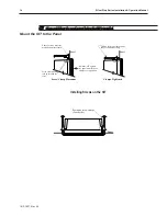
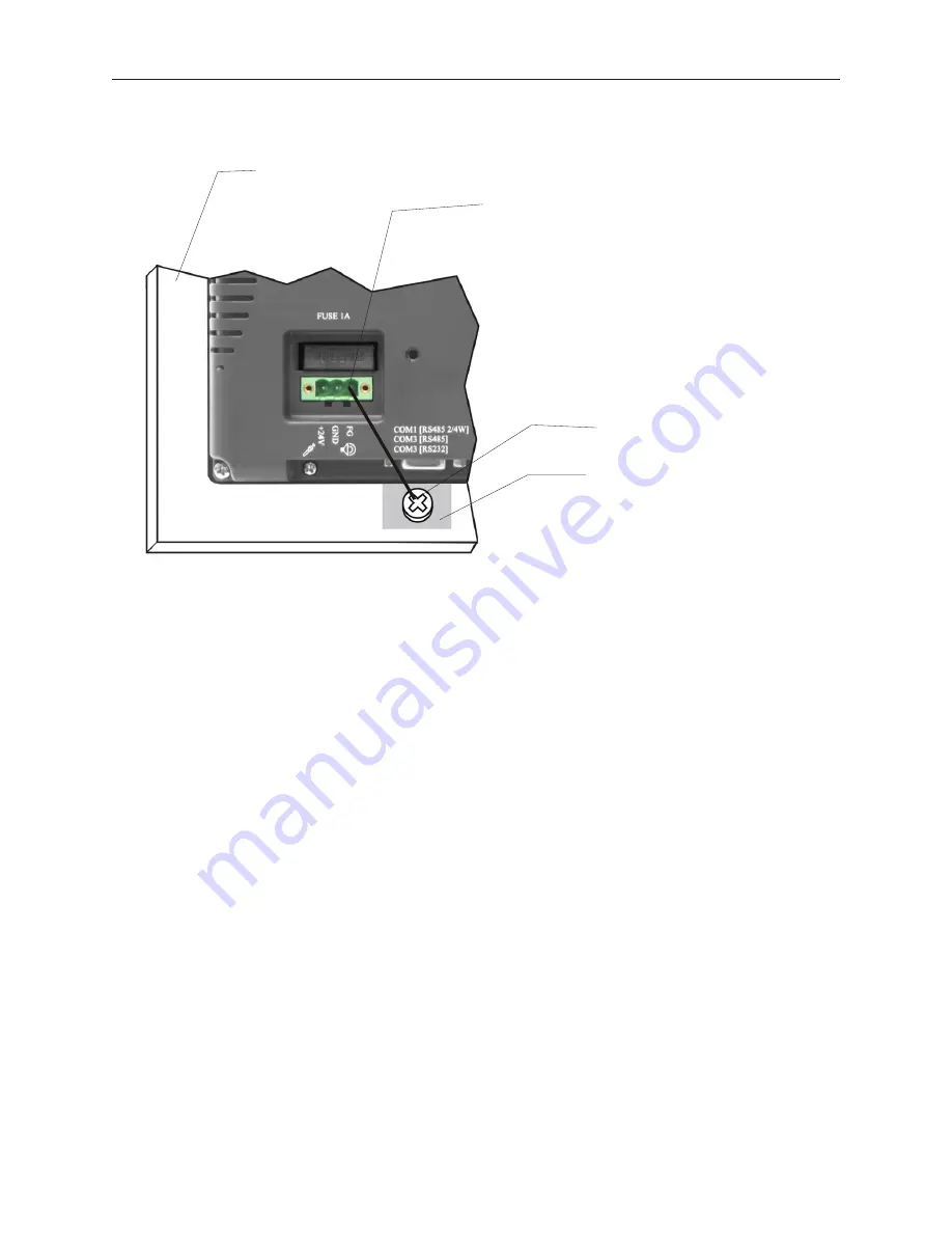
Frame ground (marked FG)
Stud or screw
Area on panel free of paint
Control panel
(connected to earth ground)
HMI5080/HMI5104/HMI5121/HMI5150 Chas sis Ground Con nec tion
Summary of Contents for Silver Plus Series
Page 20: ...1010 1007 Rev 05 16 Silver Plus Series Installation Operation Manual ...
Page 31: ...COM Ports for the HMI5056 5070 1010 1007 Rev 05 Connect the OIT to the PLC or Controller 27 ...
Page 38: ...1010 1007 Rev 05 34 Silver Plus Series Installation Operation Manual ...
Page 49: ...7 Click the Shape tab 1010 1007 Rev 05 Creating Your First Project 45 ...
Page 62: ...1010 1007 Rev 05 58 Silver Plus Series Installation Operation Manual ...
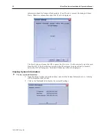
Page 75: ...3 Click OK The System Parameter Settings dialog appears 1010 1007 Rev 05 Using EZware 5000 71 ...
Page 132: ...1010 1007 Rev 05 128 Silver Plus Series Installation Operation Manual ...
Page 156: ...1010 1007 Rev 05 152 Silver Plus Series Installation Operation Manual ...
Page 210: ...1010 1007 Rev 05 206 Silver Plus Series Installation Operation Manual ...
Page 216: ...1010 1007 Rev 05 212 Silver Plus Series Installation Operation Manual ...
Page 246: ...1010 1007 Rev 05 242 Silver Plus Series Installation Operation Manual ...


