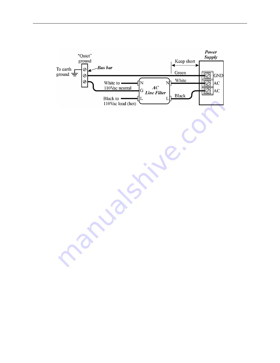
Do not use the power supply used to provide power to the OIT to power switching relays, solenoids, or other active
devices.
Ca ble Routing and Noise Im mu nity
Follow these guidelines when routing cable to the OIT:
·
Always route the OIT communication cable and the power cable away from any AC voltage or rapidly
switching DC control lines.
·
Never bundle the OIT cables together with 120VAC power wires or with relay wiring.
·
Try to keep at least 8 inches (20 cm) of separation between the OIT cables and other power wiring. If
voltages greater than 120VAC are used in the system, greater separation is required.
·
If the OIT cables must come near AC wiring, make sure they cross at 90 degrees.
·
Run AC power wires in a separate grounded conduit to reduce electrical noise interference.
·
Keep the cable lengths for the OIT as short as possible. Do not coil excess cable and place it next to AC
powered equipment.
·
Cover any equipment used in the enclosure that operates at high frequency or high current levels with a
grounded metal shield.
In stal la tion
It is necessary to follow all installation procedures described in this chapter for electrical noise immunity and CE
compliance.
Your Maple Systems OIT is designed to connect easily to your PLC. External rear connectors provide quick
connections for power, communications and programming wiring.
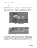
There are two connectors for serial communications on the rear of the OIT. Both of these are D-subminiature 9-pin
connectors.
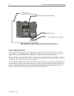
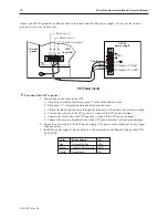
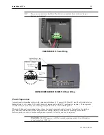
Use the supplied separate 3-position terminal block to provide power to the OIT.
Con nect the OIT to Power
The power cable for the OIT should be 18AWG, 2-conductor wire with a shield drain wire and protective shield
foil. You may buy cable P/N 6030-0009 by the foot from Maple Systems to make these.
1010-1007, Rev 05
In stal la tion of OITs
11
Power Line Fil ter Connection
Summary of Contents for Silver Plus Series
Page 20: ...1010 1007 Rev 05 16 Silver Plus Series Installation Operation Manual ...
Page 31: ...COM Ports for the HMI5056 5070 1010 1007 Rev 05 Connect the OIT to the PLC or Controller 27 ...
Page 38: ...1010 1007 Rev 05 34 Silver Plus Series Installation Operation Manual ...
Page 49: ...7 Click the Shape tab 1010 1007 Rev 05 Creating Your First Project 45 ...
Page 62: ...1010 1007 Rev 05 58 Silver Plus Series Installation Operation Manual ...
Page 75: ...3 Click OK The System Parameter Settings dialog appears 1010 1007 Rev 05 Using EZware 5000 71 ...
Page 132: ...1010 1007 Rev 05 128 Silver Plus Series Installation Operation Manual ...
Page 156: ...1010 1007 Rev 05 152 Silver Plus Series Installation Operation Manual ...
Page 210: ...1010 1007 Rev 05 206 Silver Plus Series Installation Operation Manual ...
Page 216: ...1010 1007 Rev 05 212 Silver Plus Series Installation Operation Manual ...
Page 246: ...1010 1007 Rev 05 242 Silver Plus Series Installation Operation Manual ...


