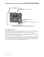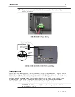
Always run the DC ground wire directly back to the signal return of the power supply.
Do not use the chassis
ground wire as your signal return.
4
To connect the OIT to power:
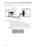
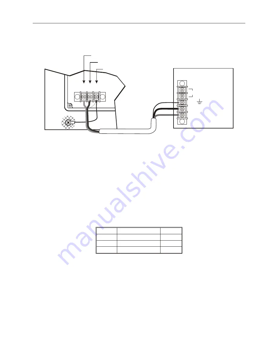
1. Connect the power cable to the OIT
a. Strip the power cable shield to expose 2” of the black and red wires.
b. Strip about ¼” of insulation from the black and red wires.
c. Thread the black and red wires through the ferrite core. The shield wire must be outside.
d. Connect the red wire to the DC positive (+) input of the OIT power terminal.
e. Connect the black wire to the DC negative (-) input of the OIT power terminal.
f. Connect the power cable shield wire to the OIT power terminal’s chassis ground input.
2. Route the power cable to the OIT power supply. The power cable should not be any longer
than necessary.
3. Install the power supply wires as follows (with colors shown for Maple Systems cable P/N
6030-0009):
Color
Power Supply
OIT
Red
+24 Vdc
+24V
Black
-24 Vdc return
GND
Shield
Case ground
FG
1010-1007, Rev 05
12
Sil ver Plus Se ries In stal la tion & Op er a tion Man ual
OIT
(rear side)
24Vdc
power supply
Control
panel
Shield wire (bare)
Black wire (-)
Red wire (+)
24V
120Vac
Black
Shield drain
Red
FG
DC Output -V (Gnd)
DC V (+24V)
(+)
GND
(-)
FG
OIT Power Inputs
Summary of Contents for Silver Plus Series
Page 20: ...1010 1007 Rev 05 16 Silver Plus Series Installation Operation Manual ...
Page 31: ...COM Ports for the HMI5056 5070 1010 1007 Rev 05 Connect the OIT to the PLC or Controller 27 ...
Page 38: ...1010 1007 Rev 05 34 Silver Plus Series Installation Operation Manual ...
Page 49: ...7 Click the Shape tab 1010 1007 Rev 05 Creating Your First Project 45 ...
Page 62: ...1010 1007 Rev 05 58 Silver Plus Series Installation Operation Manual ...
Page 75: ...3 Click OK The System Parameter Settings dialog appears 1010 1007 Rev 05 Using EZware 5000 71 ...
Page 132: ...1010 1007 Rev 05 128 Silver Plus Series Installation Operation Manual ...
Page 156: ...1010 1007 Rev 05 152 Silver Plus Series Installation Operation Manual ...
Page 210: ...1010 1007 Rev 05 206 Silver Plus Series Installation Operation Manual ...
Page 216: ...1010 1007 Rev 05 212 Silver Plus Series Installation Operation Manual ...
Page 246: ...1010 1007 Rev 05 242 Silver Plus Series Installation Operation Manual ...

