4.
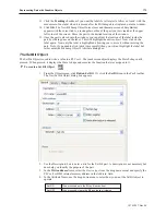
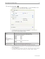
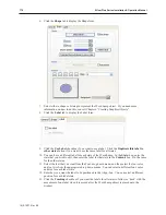
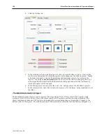
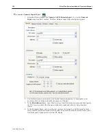
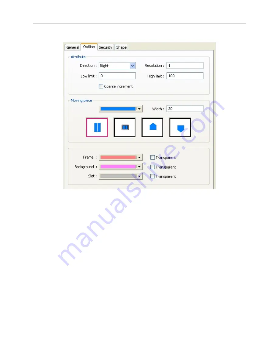
Click the Outline tab:
5.
In the Attribute section, select the
direction
that you want the slider to move. Next, set the
resolution
as the amount by which the register value changes as the slider is moved. Finally,
et the
high limit
and
low limit
as the minimum and maximum values to be written to the
register. Check the
coarse increment
check box to allow the slider to change register by a
value larger than that specified by the Resolution setting and then select the increment by
which the register will be changed.
6.
In the Moving piece section, select the
color, size
, and
appearance
of the slider’s pointer.
7.
In the colors section, select the
color
and
transparency
for the frame,
background
and
slot
of
the slider.
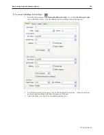
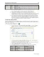
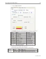
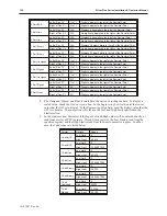
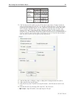
The MultiState Switch Ob ject
The MultiState Switch Object is used to represent the value of one 16-bit, 32-bit or 64-bit PLC register while
writing a 16-bit, 32-bit or 64-bit value to the same or another PLC register each time the object is pressed. The
object continuously reads one PLC register and displays the corresponding shape or bitmap that is tagged to the
defined states of the register. The touchscreen object when pressed, executes the function that was assigned to it.
1010-1007, Rev 05
182
Sil ver Plus Se ries In stal la tion & Op er a tion Man ual
Summary of Contents for Silver Plus Series
Page 20: ...1010 1007 Rev 05 16 Silver Plus Series Installation Operation Manual ...
Page 31: ...COM Ports for the HMI5056 5070 1010 1007 Rev 05 Connect the OIT to the PLC or Controller 27 ...
Page 38: ...1010 1007 Rev 05 34 Silver Plus Series Installation Operation Manual ...
Page 49: ...7 Click the Shape tab 1010 1007 Rev 05 Creating Your First Project 45 ...
Page 62: ...1010 1007 Rev 05 58 Silver Plus Series Installation Operation Manual ...
Page 75: ...3 Click OK The System Parameter Settings dialog appears 1010 1007 Rev 05 Using EZware 5000 71 ...
Page 132: ...1010 1007 Rev 05 128 Silver Plus Series Installation Operation Manual ...
Page 156: ...1010 1007 Rev 05 152 Silver Plus Series Installation Operation Manual ...
Page 210: ...1010 1007 Rev 05 206 Silver Plus Series Installation Operation Manual ...
Page 216: ...1010 1007 Rev 05 212 Silver Plus Series Installation Operation Manual ...
Page 246: ...1010 1007 Rev 05 242 Silver Plus Series Installation Operation Manual ...


